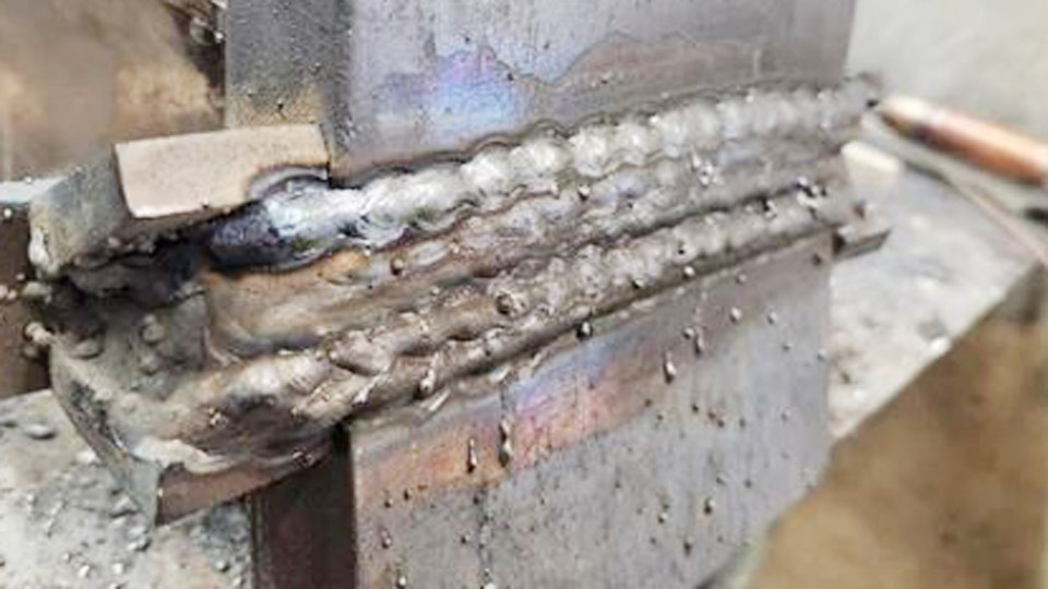
Learning How to MIG Weld Flux Core for Beginners starts with understanding that flux-cored welding behaves differently than gas-shielded MIG welding. Incorrect polarity, poor voltage and wire feed settings, or improper travel speed can quickly lead to excessive spatter, lack of fusion, burn-through, or weak welds.
Because flux core produces deeper penetration and tolerates outdoor conditions better, it is a popular choice for new welders, but only when the machine is set up correctly and basic welding techniques are applied consistently.
Developing good habits from the start improves arc stability, bead appearance, and overall weld strength while reducing wasted wire, grinding, and costly rework. This guide provides a practical foundation for beginners so you can produce cleaner, stronger welds with greater confidence on common mild steel projects.
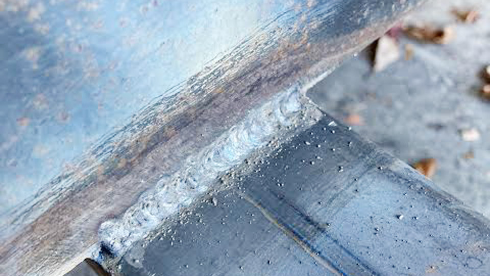
Image by r/Welding
Equipment and Setup Decisions
Choosing Flux Core Wire Diameter and Type
Wire diameter directly controls deposition rate, penetration, and heat input. For most beginner and hobby machines (up to 200A), 0.030″ wire handles 16-gauge to 3/16″ material effectively. It runs cooler and reduces burn-through risk on thin stock.
Switch to 0.035″ for 1/8″ and thicker sections. This diameter supports higher wire feed speeds and deeper penetration on structural steel while maintaining arc stability. Common all-position self-shielded wires include E71T-GS (general purpose) and E71T-11 (better mechanical properties).
Avoid gas-shielded flux core (FCAW-G) unless running dual-shield with external gas, as it requires different polarity and setup.
Key decision: Match wire diameter to your machine’s output and typical material thickness. Test on scrap first—0.030″ for portability and thin work; 0.035″ for speed on heavier plate.
Polarity and Machine Configuration
Self-shielded flux core runs on DCEN (electrode negative, straight polarity). This concentrates ~70% of heat into the workpiece for better penetration and flux activation. Most MIG machines default to DCEP for solid wire, so swap the polarity cables at the feeder or polarity block.
Use knurled drive rolls sized for your wire diameter. Set drive roll tension low enough that you can stop the wire with firm finger pressure but without slippage.
Excessive tension flattens the tubular wire and causes birdnesting. Install the correct contact tip (usually matching wire size) and ensure the liner is clean and straight.
Grounding and Initial Preparation
Clamp the work lead to clean, bare metal as close as possible to the weld zone. Poor grounding creates unstable arcs and voltage drops. Remove mill scale, rust, paint, and oil from the joint area—flux core tolerates some contamination better than solid wire but performs best on clean surfaces for minimal porosity.
Understanding and Setting Welding Parameters
Voltage, Wire Feed Speed, and Amperage Relationships
Voltage primarily controls arc length and bead width. Wire feed speed (WFS) determines amperage and deposition rate. Higher WFS increases current draw and penetration; higher voltage flattens the bead and reduces convexity.
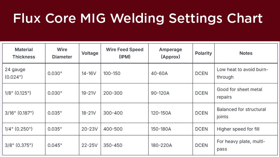
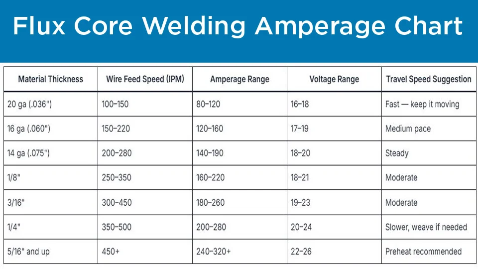
Start with manufacturer charts on the welder lid, then fine-tune on scrap. Listen for a steady “bacon frying” crackle—erratic popping indicates voltage too low; a hissing sound means voltage too high.
Typical starting ranges for self-shielded E71T-11 flux core on mild steel (flat position, ~3/4″ stickout):
| Material Thickness | Wire Diameter | Voltage (V) | WFS (IPM) | Approx. Amps | Notes |
|---|---|---|---|---|---|
| 16-18 ga | 0.030″ | 16-18 | 150-250 | 60-110 | Stringer beads; avoid burn-through |
| 1/8″ | 0.030″ or 0.035″ | 17-20 | 200-300 | 90-140 | Good for fillets |
| 3/16″ | 0.035″ | 18-22 | 250-350 | 120-170 | Multi-pass if needed |
| 1/4″ | 0.035″ | 19-23 | 300-400 | 140-190 | Strong single-pass root |
| 3/8″+ | 0.045″ | 20-24 | 350-480 | 160-220 | Weave or multi-pass; preheat heavy plate |
Adjust one variable at a time. Increase WFS for more penetration; raise voltage slightly for wider, flatter beads. These are starting points—actual values vary by machine, torch length, and joint fit-up.
Stickout (CTWD) and Its Impact
Maintain 5/8″ to 3/4″ contact tip to work distance (CTWD) for self-shielded flux core—roughly double solid wire MIG. Longer stickout allows flux to generate shielding gas effectively but reduces current and can cause porosity if excessive. Shorter stickout risks burnback into the tip.
Measure from the contact tip to the workpiece. Keep it consistent; variations cause arc instability. For overhead or restricted access, shorten slightly but monitor for spatter.
Core Welding Techniques
Gun Angles and Travel Direction
Use a drag (pull) technique: point the gun back toward the completed weld at a 5-15° travel angle from vertical. “If there’s slag, you drag.” This keeps the arc ahead of the slag pool and promotes proper coverage.
Work angle depends on the joint:
- Butt joints: 90° (perpendicular).
- T-joints: 45° into the joint.
- Lap joints: 60-70° to direct heat into the root on thicker material.
Exceeding 20° travel angle pulls in atmospheric gases, causing porosity. In vertical-up welding, a slight push may help control the puddle on thin material, but default to drag for beginners.
Travel Speed and Puddle Control
Travel speed must keep the leading edge of the puddle under the wire tip. Too fast produces narrow beads with lack of fusion; too slow causes excessive buildup, slag entrapment, or burn-through.
Target 8-12 IPM on 1/8″ material; slow to 5-8 IPM on 1/4″+. Watch the puddle shape—it should be fluid but not runny. Use a slight weave or triangle motion on wider gaps or vertical welds to build shelves and ensure tie-in at the toes.
Position-Specific Adjustments
Flat position: Straight drag with minimal weaving. Easiest for consistent beads.
Horizontal: Tilt gun upward 10° to prevent sagging. Pause briefly at the toes during weaves.
Vertical up: Use a triangle or slight crescent weave. Maintain higher travel angle (closer to 10-15°) and slightly faster speed to control the puddle. Build in layers.
Overhead: Shorten stickout slightly, reduce parameters by 10-15%, and use stringer beads. Gravity pulls the puddle—keep travel steady to avoid drops.
Joint Preparation and Multi-Pass Strategies
Proper joint design prevents defects. For butt joints thicker than 1/4″, bevel edges to 30-35° with a 1/16″-1/8″ root face for full penetration. Clean each pass thoroughly—chip and wire brush slag before the next layer. Incomplete slag removal leads to inclusions.
In multi-pass welds, stagger starts and stops to avoid stress concentrations. Use stringer beads for strength in critical applications; weaves fill wider joints faster but require more skill to prevent undercut.
Preheat thick or high-carbon steel to 200-300°F to reduce cracking risk. Maintain interpass temperature below 350°F for most mild steel.
Troubleshooting Common Flux Core Issues
Porosity: Caused by contamination, excessive stickout, wind, or moisture. Clean metal aggressively and maintain consistent CTWD. Shorten stickout or reduce voltage if persistent.
Excessive spatter: Voltage too low or WFS too high. Increase voltage slightly and ensure correct polarity. Anti-spatter spray helps on the nozzle.
Lack of fusion/undercut: Travel speed too fast or insufficient heat. Slow down, increase WFS, or adjust gun angle to direct arc into the root.
Slag inclusions: Poor cleaning between passes or improper travel angle allowing slag to roll ahead. Increase drag angle and travel speed.
Birdnesting or burnback: Drive roll tension, liner issues, or incorrect contact tip. Use knurled rolls and proper tension. Maintain stickout to prevent burnback.
Worm tracks: Often excessive voltage or moisture. Lower voltage and store wire in a dry environment.
Test parameters on scrap matching your project. Read the bead: convex with good tie-in indicates balance; undercut or ropey beads need adjustment.
When to Choose Flux Core vs. Solid Wire MIG
Flux core excels outdoors, on dirty or rusty metal, and for high-deposition work. It tolerates wind up to 15-20 mph where gas shielding fails.
However, it produces more spatter and slag, requiring post-weld cleanup. Solid wire with gas delivers cleaner beads and better appearance for indoor shop work on clean material.
For critical structural or code work, verify wire classification and follow qualified procedures. Flux core deposition rates often exceed solid wire by 20-40% on thicker plate.
Wrapping Up
The strongest flux core welds result from precise setup decisions—correct DCEN polarity, consistent 3/4″ stickout, drag technique, and parameters tuned to your exact wire and thickness—rather than chasing perfect beads on the first try.
In real-world applications like trailer repairs or gate fabrication, these choices deliver joints that withstand vibration and load far better than mismatched settings.
As you advance, experiment with weave patterns and multi-pass techniques on heavier plate to achieve radiographic-quality results with flux core’s high deposition advantage.
FAQ
What polarity do I need for flux core MIG welding?
Self-shielded flux core requires DCEN (electrode negative). Swap cables so the gun is negative and work clamp positive. Wrong polarity causes poor penetration and heavy spatter.
How do I reduce spatter when MIG welding with flux core?
Maintain 5/8″-3/4″ stickout, use correct voltage/WFS balance, and ensure clean metal. Slightly higher voltage often smooths the arc. Knurled rolls and proper tension also help.
Can I use flux core wire without gas on a standard MIG welder?
Yes, that’s the main advantage of self-shielded wire. No external gas needed, but polarity must be DCEN and technique adjusted to drag.
What thickness of metal is flux core MIG best for?
Best for 1/8″ and thicker mild steel. It works on thinner material with care (lower settings, stringers), but solid wire is often easier below 16 gauge to avoid burn-through.