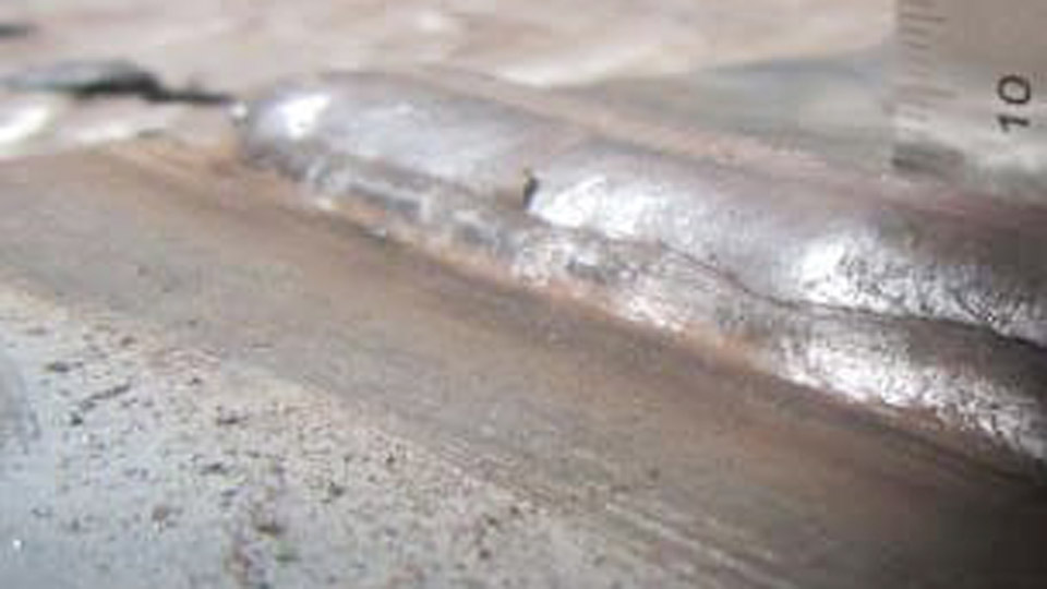
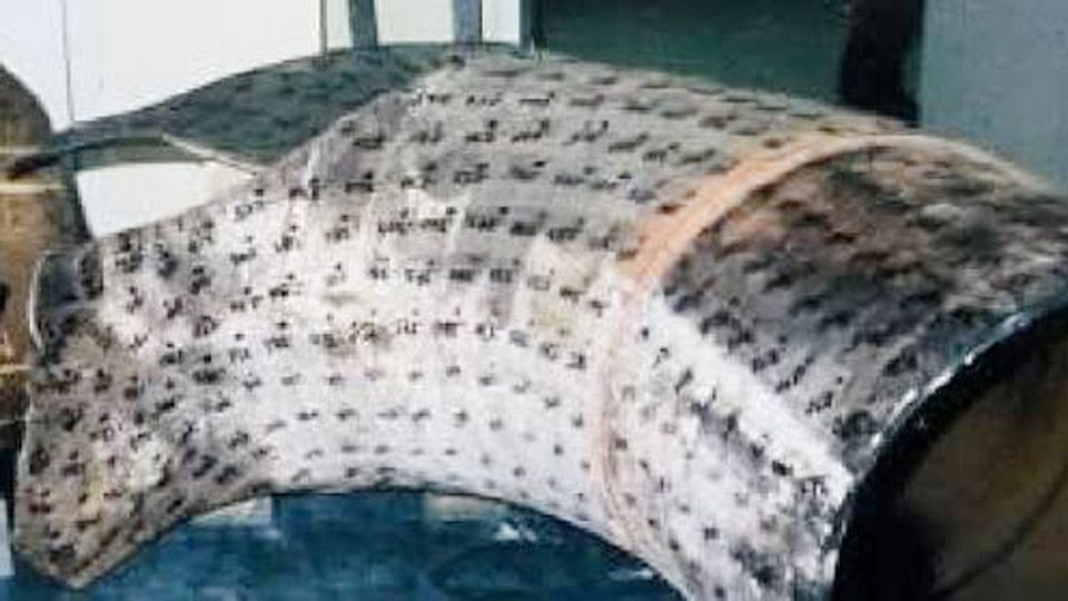
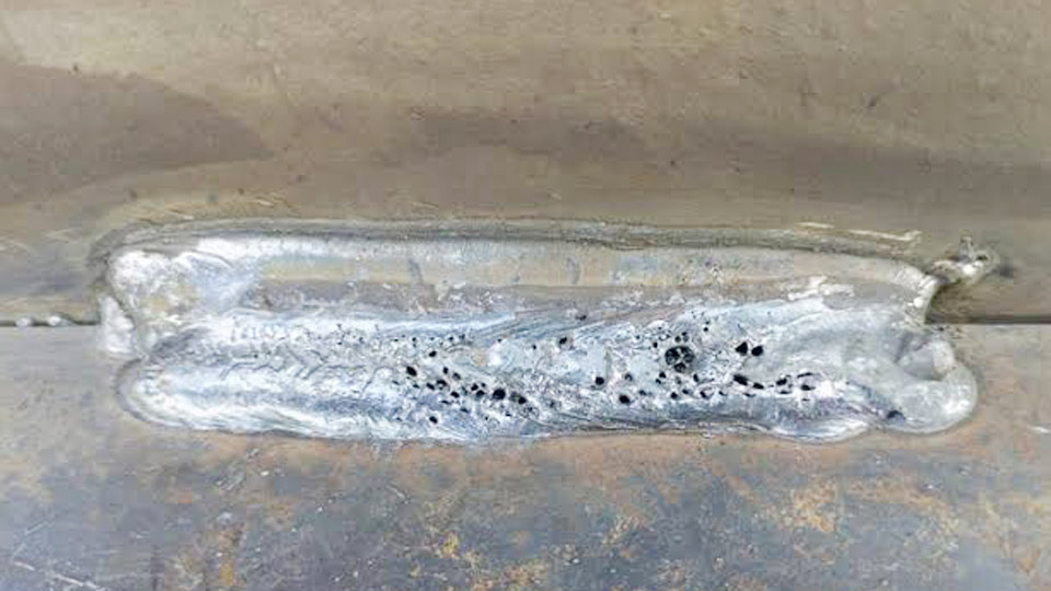
Lack of Fusion in Welding is one of the most critical weld discontinuities because it prevents the weld metal from fully bonding with the base metal or previous weld passes. Even when a weld appears sound on the surface, incomplete fusion can significantly reduce joint strength, increase the risk of cracking under load, and cause failures during visual or non-destructive inspection.
This defect is commonly linked to incorrect welding parameters, poor torch or electrode angle, excessive travel speed, contaminated surfaces, or inadequate heat input.
Identifying the root cause is essential for producing structurally reliable welds and avoiding costly repairs or rejected fabrications.
Understanding how lack of fusion develops—and the practical techniques used to eliminate it—helps welders improve penetration, meet code requirements, and consistently produce stronger, higher-quality welds across a wide range of welding processes.
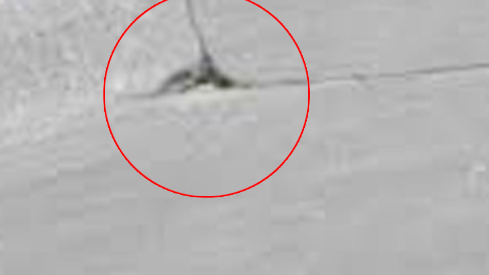
Image by onestopndt
What Causes Lack of Fusion in Welding
Lack of fusion arises when the arc energy fails to melt the base metal or previous bead sufficiently for metallurgical bonding at the interface. This produces a weak, crack-like plane rather than a continuous fusion zone.
Insufficient Heat Input and Parameter Mismatches
Low heat input ranks as the dominant cause. Welding current below the required range, voltage mismatched to the transfer mode, or excessive travel speed prevents the weld pool from achieving the necessary temperature and fluidity for sidewall and root fusion.
In short-circuit MIG on thicker sections, this manifests as classic cold lap defects where high deposition meets low heat transfer.
For example, on 6 mm mild steel with MIG, currents below 150–180 A often produce shallow beads that sit atop unmelted base metal. Heat input calculations (typically H = (V × A × 60) / (1000 × TS) in kJ/mm, adjusted by process efficiency) must stay within WPS minimums to ensure fusion.
Travel speeds exceeding the deposition rate exacerbate this, especially in downhill positions where the pool rolls ahead of the arc.
Joint Preparation and Fit-Up Issues
Narrow groove angles restrict arc access to sidewalls, while excessive root face thickness or insufficient root gap shadows areas from heat. Misalignment further compounds problems by creating uneven fusion opportunities. In multi-pass welds, poor inter-pass cleaning leaves slag or oxides that act as barriers.
Typical minimum groove geometries include 60° included angles for many processes, with root gaps of 2–4 mm depending on the method. Deviations here force compensatory increases in heat that risk other defects like distortion.
Surface Contamination and Material Factors
Mill scale, rust, oil, paint, or oxides prevent wetting even with adequate heat. These create thermal and physical barriers, particularly on aluminum (oxide layer) or weathered steel. Contaminants vaporize partially but leave unfused interfaces.
Magnetic arc blow in ferromagnetic materials deflects the arc, preferentially melting one side and leaving the opposite unfused. This is more pronounced in DC processes with poor clamp placement.
Process-Specific Causes and Parameter Adjustments
Different welding processes exhibit unique vulnerabilities to lack of fusion based on their heat delivery and operator control.
MIG/MAG (GMAW) and FCAW Challenges
Short-circuit transfer in MIG is highly susceptible on thicker materials due to inherently lower heat. Spray or pulsed modes generally perform better but still fail with high travel speeds or excessive stick-out. Wrong torch angle (push instead of drag in some cases) or long stick-out reduces effective current and penetration.
Adjust voltage to match wire feed speed for stable transfer. For 0.035″ wire on mild steel, typical ranges shift from 18–22 V and 200–300 IPM wire speed depending on thickness. Maintain 3/8″ maximum stick-out and direct the arc at the leading pool edge toward sidewalls.
SMAW (Stick) Welding Vulnerabilities
Large-diameter electrodes in narrow grooves limit access, while low amperage produces sluggish pools. Incorrect electrode angle fails to wash into sidewalls. Cellulose electrodes tolerate some variation better than low-hydrogen types, which demand stricter control.
Use amperage charts: 3.2 mm electrodes typically run 90–150 A flat. Maintain short arc length and employ weave techniques with dwells at sidewalls.
GTAW (TIG) Specific Considerations
TIG offers excellent control but suffers from insufficient filler addition timing or low current. Oxide on aluminum requires thorough cleaning and AC balance adjustment. Technique errors like improper torch angle or filler rod placement create gaps.
Root passes demand precise root face and gap control (e.g., 0–1 mm root face). Higher currents with pulsed modes help on thicker sections while controlling heat input.
Detecting Lack of Fusion: Methods and Limitations
Lack of fusion is notoriously difficult to detect because it is often subsurface and planar, oriented parallel to inspection beams.
Visual and Surface Inspection
Surface-breaking lack of fusion may show as irregular bead edges, undercuts, or lack of tie-in. However, this misses the majority of internal defects. Use magnification and proper lighting, but never rely on visuals alone for critical welds.
Nondestructive Testing (NDT) Approaches
Radiography (RT) struggles with tight, planar defects aligned with the beam, often underestimating severity. Ultrasonic testing (UT), especially phased array (PAUT), excels at detecting planar reflectors from various angles through strong echo returns. UT is the preferred method for subsurface lack of fusion.
Magnetic particle or dye penetrant works for surface indications. In production, real-time thermal monitoring can flag cold fusion zones during welding.
Destructive testing on test coupons—bend or macro-etch—provides definitive verification during procedure qualification.
Preventing Lack of Fusion: Technical Controls and Best Practices
Prevention centers on consistent heat delivery to fusion faces, proper access, and clean interfaces.
Optimizing Heat Input and Welding Parameters
Follow qualified WPS ranges for current, voltage, and travel speed. Increase current or reduce speed to boost heat input without exceeding maximums that cause distortion. For multi-pass work, calculate cumulative effects. Test parameters on scrap matching the production material and thickness.
Maintain short arc lengths for focus. In MIG, match transfer mode to application—avoid short-circuit on heavy sections unless parameters are tightly controlled.
Technique and Arc Manipulation
Direct the arc toward the joint face and leading edge of the pool, not buried in molten metal. Use 5–15° work angle adjustments in groove welds to address each sidewall. Employ controlled weaves with sidewall dwells to promote washing action. Avoid excessive pool size that floods ahead of the arc.
In vertical or overhead positions, adjust travel to prevent downhill rollover. Proper gun or electrode angles prevent preferential melting.
Joint Design, Preparation, and Fit-Up
Specify adequate bevel angles (minimum 60° common), root gaps, and faces per process. Verify fit-up with gauges before tacking. Wider preps improve access at the cost of more filler but reduce repair risks.
Grind or brush all fusion surfaces to bright metal within the heat-affected zone (at least 25 mm). Remove moisture and use preheat where specified to slow cooling and aid fusion.
Equipment and Environmental Controls
Ensure stable power sources, clean contact tips, and proper gas flow (20–25 CFH typical for MIG). Minimize drafts with screens. Position ground clamps to reduce arc blow; consider AC for SMAW when feasible. Demagnetize materials if needed.
Regularly inspect torches, liners, and nozzles for wear that affects arc stability.
Repairing Lack of Fusion Defects
Repair requires complete removal of the defective area by grinding or gouging to sound metal, followed by re-welding per the original or qualified procedure. Partial repairs often fail due to residual discontinuities. For critical applications, re-inspect with UT after repair. Document all steps for traceability.
Prevention during initial welding is far more efficient than post-weld repairs, which add significant time and cost.
Real-World Decision Making for Welders
When setting up a weld, prioritize joint prep verification and parameter testing over speed. On a structural project with 1/2″ plate, for instance, opting for slightly wider grooves and verified 180+ A MIG settings avoids UT failures that delay production.
Professionals balance productivity with quality by qualifying procedures that incorporate realistic shop conditions, including position and material variations.
DIY and hobby welders benefit from scrap testing and macro-etches to build intuition for proper fusion appearance and sound. Students should master heat input calculations early, as they underpin decisions across processes.
Wrapping Up
Strong welds result from deliberate control of fusion variables rather than reactive fixes. Master heat input calculations, joint access, and arc placement for reliable performance across materials and positions.
In advanced applications, integrating real-time monitoring with qualified procedures pushes defect rates near zero while maintaining productivity. This technical discipline separates adequate welds from those that endure under demanding service conditions. (Word count: approx. 2,150)
FAQ
What is the main difference between lack of fusion and lack of penetration?
Lack of fusion involves failure to bond with sidewalls or previous beads despite weld metal presence, while lack of penetration means the weld metal does not reach the required depth through the joint thickness. Both weaken structures but require different troubleshooting—fusion focuses more on technique and cleanliness, penetration on root parameters.
Can lack of fusion be acceptable in any welds?
In most codes (e.g., ASME, AWS), lack of fusion is rejectable for critical applications like pressure vessels or load-bearing structures. Minor surface indications might be tolerated in non-critical, low-load scenarios per specific acceptance criteria like ISO 5817 levels, but it is rarely acceptable without engineering evaluation.
How does travel speed affect lack of fusion risk?
Excessive travel speed reduces heat input per unit length, leading to shallow pools and unfused interfaces. Optimal speed allows the pool to wet fusion faces fully without flooding ahead of the arc. Test and adjust based on thickness and process—slower for thicker materials or root passes.
What NDT method best detects subsurface lack of fusion?
Phased array ultrasonic testing (PAUT) is superior for planar defects due to its sensitivity to reflectors at various orientations. Conventional UT also performs well; radiography is less reliable for tight lack of fusion.