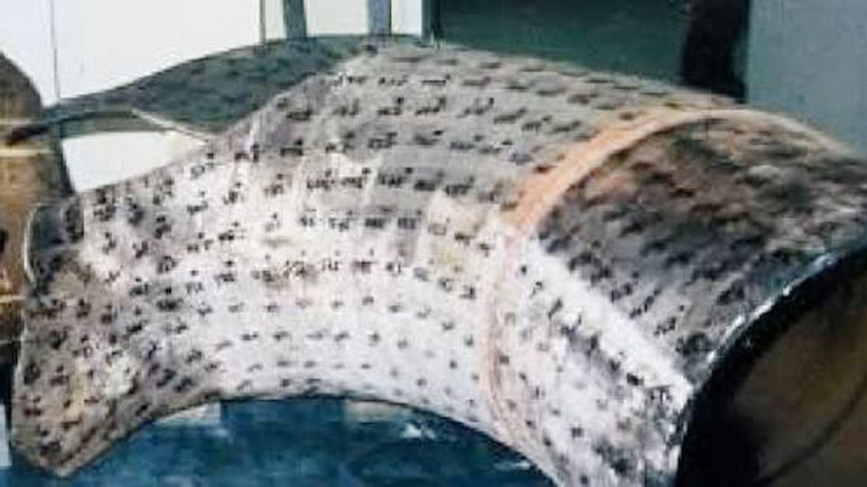
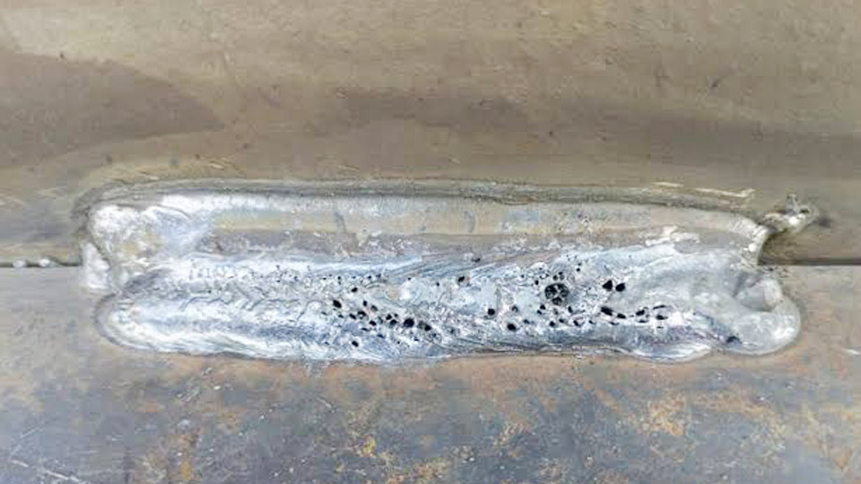
Cracks are among the most critical welding defects because they can weaken a joint, reduce structural integrity, and cause a weld to fail during service or inspection.
Understanding what are the causes and remedies of cracks in welding is essential for preventing costly rework, rejected welds, and unexpected failures in fabrication, construction, and repair projects.
Cracking can result from excessive heat input, rapid cooling, improper filler metal selection, joint restraint, hydrogen contamination, or poor welding parameters. If the underlying cause is not identified, simply repairing the crack often leads to the same defect returning.
Knowing how different crack types develop—and the corrective actions that address each one—helps welders produce stronger, more reliable welds while maintaining compliance with quality standards and minimizing downtime in real-world welding applications.
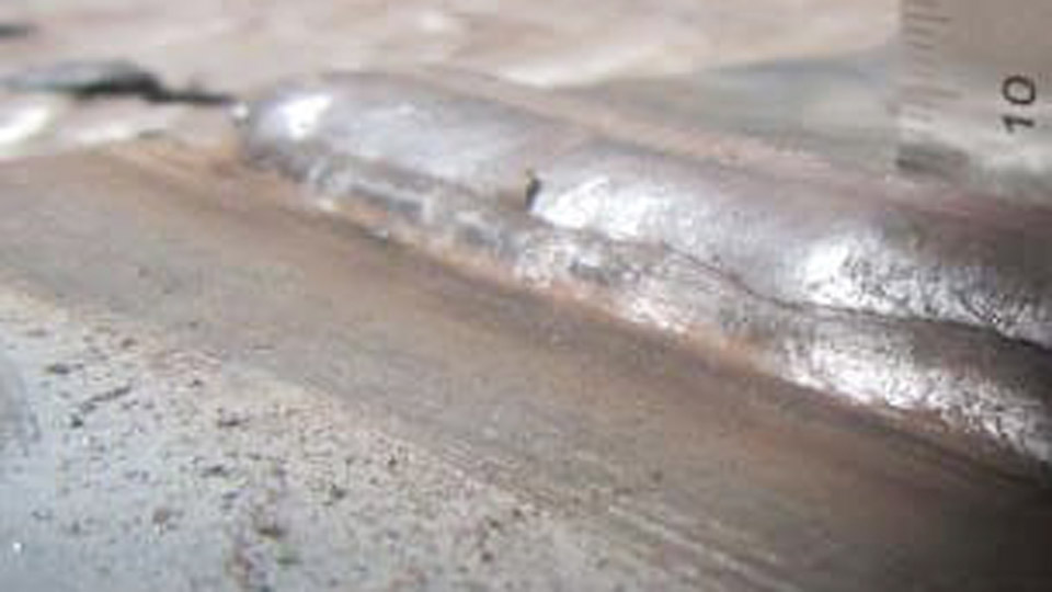
Image by technoweld
Types of Welding Cracks: Classification and Characteristics
Hot Cracks (Solidification Cracks)
Hot cracks form during or immediately after solidification, typically at temperatures above 1000°F (538°C). They occur in the weld metal as the molten pool freezes, often along the centerline or in the crater due to segregation of low-melting-point impurities like sulfur and phosphorus.
These cracks are intergranular, following grain boundaries weakened by eutectic films. Longitudinal centerline cracks appear straight along the weld axis, while crater cracks form star-shaped patterns at abrupt arc terminations.
They are visible shortly after welding and stem from shrinkage stresses pulling on semi-solid metal with insufficient ductility.
Susceptible materials include austenitic stainless steels, high-carbon steels, and aluminum alloys with wide solidification ranges. High depth-to-width bead ratios (deeper than wide) and high restraint exacerbate the issue by concentrating contraction strains.
Cold Cracks (Hydrogen-Induced Cracking)
Cold cracks, also called delayed or hydrogen-induced cracks (HICC), develop after the weld cools, sometimes hours or days later. They require three simultaneous conditions: diffusible hydrogen, a susceptible microstructure (such as martensite in the HAZ), and tensile residual stresses.
These cracks often appear in the heat-affected zone (HAZ) or weld metal as underbead, toe, or root cracks. They propagate transgranularly or intergranularly and are common in carbon-manganese and low-alloy steels with carbon equivalents (CE) above 0.40.
Hydrogen sources include moisture in electrodes, flux, shielding gas, or surface contaminants like oil, rust, or paint.
Other Crack Types: Crater, Lamellar Tearing, and Reheat Cracks
Crater cracks are a subset of hot cracks at weld ends. Lamellar tearing occurs in rolled plates with inclusions (e.g., MnS stringers) under through-thickness strain, appearing step-like in the base metal. Reheat cracks form during post-weld heat treatment (PWHT) in creep-resistant alloys like Cr-Mo steels due to grain boundary embrittlement.
Primary Causes of Cracks in Welding
Thermal and Solidification Factors
Rapid cooling creates steep thermal gradients and high contraction stresses. Excessive heat input enlarges the weld pool and HAZ, promoting coarse grains and segregation that lower hot ductility. Conversely, low heat input on thick sections can cause fast cooling and brittle microstructures.
Joint restraint prevents free contraction, elevating residual tensile stresses. Poor fit-up, thick sections, and rigid fixtures increase this effect. Bead geometry matters: high depth-to-width ratios (>1:1.5) trap stresses in the center.
Hydrogen and Contamination Effects
Hydrogen diffuses into the weld pool and recombines at defects or grain boundaries, generating pressure that initiates cracks under stress. Critical for steels with hardenability. Contaminants on base metal or consumables introduce moisture or other gases.
Material Composition and Metallurgy
High sulfur (>0.025%) or phosphorus promotes hot cracking by forming low-melting films. High carbon equivalent (CE = C + Mn/6 + (Cr+Mo+V)/5 + (Ni+Cu)/15) increases hardenability and cold cracking risk. Impurities in filler metals or base plates (e.g., tramp elements like Sn, Sb) worsen reheat cracking.
Procedural and Technique Issues
Abrupt arc stops create unfilled craters. Incorrect electrode angles, travel speeds, or sequences lead to uneven stress distribution. Using cellulosic electrodes (high hydrogen) on crack-sensitive steels without controls is a common error.
Remedies and Prevention Strategies
Consumable Selection and Hydrogen Control
Choose low-hydrogen consumables (e.g., E7018, H4 or H8 designations) for steels prone to cold cracking. Bake electrodes per manufacturer specs (typically 300–350°C for 1–2 hours) and store in heated ovens.
Use GMAW with solid wire for lower hydrogen than SMAW or FCAW. Clean base metal thoroughly to remove rust, oil, moisture, and coatings.
For hot cracking, select fillers with matching or slightly over-alloyed composition to improve ductility and refine grain structure. Limit sulfur and phosphorus in base and filler materials.
Preheat, Interpass Temperature, and Cooling Control
Preheat slows cooling rates, reduces HAZ hardness, and allows hydrogen diffusion. Calculate based on thickness, CE, and hydrogen level. For mild steel up to 1 inch thick, 50–150°F may suffice; high-strength or thicker sections often need 150–300°F or more.
Maintain interpass temperatures (typically within 50–100°F of preheat) and use insulating blankets for slow cooling. Post-weld hydrogen bake-out at 200–350°C for 1–4 hours helps on critical jobs before full PWHT.
Heat Input and Welding Parameters
Balance heat input (HI = (Voltage × Amperage × 60) / Travel Speed in ipm) to avoid extremes. Target moderate values for the material—e.g., 1.0–2.5 kJ/mm for many steels.
Use stringer beads or controlled weaving to keep depth-to-width ratio around 1:1.5 to 1:2. Decrease travel speed or increase wire feed for thicker deposits that resist shrinkage.
Joint Design, Sequencing, and Restraint Management
Design joints with adequate bevels and root gaps for good fusion without excessive restraint. Use backstep welding, block sequencing, or balanced welding on both sides of symmetric joints to distribute stresses. Buttering layers on high-restraint areas can help.
Avoid starting/stopping in high-stress zones; fill craters by pausing and adding filler or using current decay (crater fill function).
For lamellar tearing, improve through-thickness properties with Z-grade steels or modify joint design to reduce strain (e.g., avoid T-joints on thick plates when possible).
Post-Weld Heat Treatment (PWHT)
PWHT relieves residual stresses and tempers microstructures. Typical temperatures: 1100–1200°F for carbon steels, higher for alloys. Hold time depends on thickness (1 hour per inch minimum). For reheat cracking-prone materials, control heating rates and use low-impurity fillers.
Inspection and Repair Protocols
Visual, magnetic particle (MT), dye penetrant (PT), ultrasonic (UT), or radiographic (RT) testing detects cracks. For hydrogen cracks, delay final inspection 24–48 hours. Repair by gouging out the crack completely (remove 1/8–1/4 inch beyond visible ends), cleaning, and re-welding with qualified procedures. Re-inspect after repair.
Material-Specific Considerations
Carbon and Low-Alloy Steels
Focus on CE calculation and preheat charts (e.g., from EN 1011 or AWS D1.1). Higher CE demands stricter hydrogen control and thermal management. Quenched and tempered steels like ASTM A514 require careful max interpass limits to preserve properties.
Stainless Steels and Non-Ferrous Alloys
Austenitic stainless risks hot cracking due to solidification mode; use fillers promoting ferrite for better resistance. Aluminum alloys are sensitive to hot cracking from wide freezing ranges—control heat input and use proper filler (e.g., 4043 or 5356).
High-Restraint or Thick Sections
Combine higher preheat, peening (where allowed), and sequencing. Consider mechanical stress relief or vibration methods as supplements, though thermal methods remain primary.
Advanced Techniques for Crack Mitigation
Use pulsed GMAW or GTAW for better control of heat input and pool dynamics. Arc oscillation or magnetic stirring can refine weld metal grains, improving resistance to solidification cracking. For critical applications, simulate procedures with software or test plates to validate parameters.
Monitor with thermocouples or infrared for precise thermal profiles. In production, qualify WPS with bend, tensile, and impact testing plus macro-etching for crack-free sections.
Decision-Making Framework for Crack-Free Welding
Evaluate material (CE, thickness, condition), joint (restraint, design), process (hydrogen potential), and environment. Select low-hydrogen consumables, apply appropriate preheat and interpass control, optimize parameters for balanced heat input and bead shape, use proper sequencing, and verify with delayed inspection. On high-value or safety-critical welds, incorporate PWHT and non-destructive testing.
This systematic approach shifts welding from trial-and-error to predictable results, minimizing downtime and maximizing joint performance.
In demanding applications, treat cracking as a systems problem where consumable hydrogen level, exact thermal cycle (t8/5 cooling time), and joint stiffness interact.
Mastering carbon equivalent calculations, bead sequencing, and real-time thermal monitoring separates reliable fabrication from repeated failures. Prioritize procedure qualification and disciplined execution over reactive fixes for consistent, high-performance welds.
FAQ
How do you identify hot cracks versus cold cracks in a weld?
Hot cracks appear during or right after welding, often centerline or crater, with oxidized surfaces. Cold cracks show up later (hours to days), frequently in the HAZ or toe, and may require NDT for detection. Timing and location are key indicators.
What preheat temperature is typically needed to prevent cold cracking?
It depends on CE, thickness, and hydrogen level—often 150–250°F or higher for medium-carbon or alloy steels over 1 inch thick. Always consult code charts or WPS; measure 3 inches from the joint.
Can cracks in welds be repaired successfully?
Yes, if fully excavated, the area cleaned, and re-welded per qualified procedures with the same controls (preheat, low-H, etc.). Partial repairs often fail due to residual crack tips. Re-inspect thoroughly.
Does post-weld heat treatment always prevent cracking?
PWHT relieves stresses and tempers microstructures but cannot repair existing cracks. It works best preventively when combined with proper preheat and low-hydrogen practices. Immediate hydrogen bake-out may be needed first.