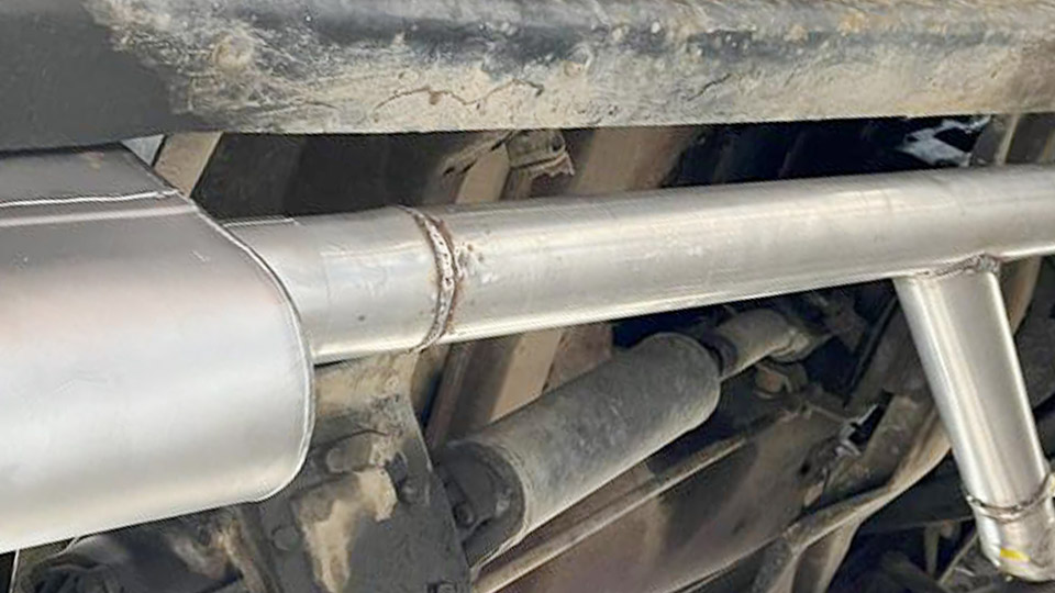
Hot Cracking vs Cold Cracking in Welding is a critical comparison because these defects form under different conditions, require different prevention methods, and can lead to costly weld failures if misidentified.
Hot cracking develops during weld solidification, while cold cracking typically appears after the weld has cooled, often due to hydrogen, residual stress, or hardened microstructures.
Knowing which defect you are dealing with directly affects welding procedure selection, filler metal choice, preheat requirements, and post-weld inspection results.
Misdiagnosis can result in rejected welds, expensive rework, reduced structural integrity, and unexpected service failures in fabricated components.
Understanding the differences between hot and cold cracking allows welders, inspectors, and fabricators to identify root causes more accurately, apply the correct preventive measures, and produce stronger, more reliable welds across a wide range of materials and welding applications.
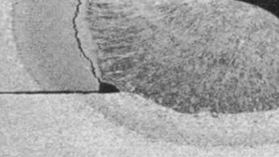
Image by welderdestiny
Understanding Hot Cracking: Formation During Solidification
Hot cracking, also called solidification cracking, occurs at high temperatures—typically above 1000°F (538°C)—during or immediately after weld pool solidification. It manifests while the weld metal remains partially liquid and vulnerable to shrinkage strains.
Mechanisms of Solidification and Liquation Cracking
As the weld pool cools, solidification proceeds from the fusion boundaries inward. Elements with low melting points, such as sulfur (S) and phosphorus (P), segregate to the centerline, forming low-melting eutectic films along grain boundaries. Transverse shrinkage stresses tear these weak films, producing centerline cracks.
Liquation cracking occurs in the HAZ or partially melted zone when low-melting constituents at grain boundaries remelt due to the welding thermal cycle, then fail under strain. This is common in materials with wide solidification ranges or impurities.
Ductility-dip cracking (DDC) appears in certain nickel alloys and austenitic stainless steels in a specific high-temperature range where ductility drops sharply, even below the solidus, due to grain boundary sliding issues.
Key Factors Influencing Hot Cracking Susceptibility
Impurities and Composition: Sulfur >0.010–0.035% and phosphorus >0.015% sharply increase risk. High carbon, silicon, and certain elements like niobium widen the brittle temperature range.
Weld Bead Geometry: Depth-to-width ratio >1:1 (deep, narrow beads) promotes centerline segregation. Ideal ratio is 1:1 to 1.4:1 for balanced solidification.
Solidification Mode: In austenitic stainless steels, primary austenitic solidification (A or AF mode) heightens susceptibility compared to ferritic-austenitic (FA) modes that incorporate delta ferrite (target 3–8 FN) to tie up impurities.
Restraint and Heat Input: High restraint amplifies shrinkage stresses. Excessive heat input enlarges the mushy zone; very low input can cause rapid solidification without adequate feeding.
Materials Most Prone to Hot Cracking
Fully austenitic stainless steels (e.g., 310, 330), high-sulfur carbon steels, aluminum alloys, and nickel-based superalloys show elevated risk. Duplex stainless steels generally resist due to primary ferritic solidification but can crack under high restraint or specific FCAW conditions.
Carbon steels with poor impurity control also suffer, especially in high-speed processes creating teardrop-shaped pools.
Cold Cracking: Delayed Hydrogen-Induced Failure
Cold cracking, or hydrogen-assisted cracking (HAC), develops at low temperatures—below ~200–600°F (93–316°C)—often hours or days after cooling. It requires three simultaneous conditions: diffusible hydrogen, a susceptible brittle microstructure (e.g., martensite), and high tensile residual stresses.
How Hydrogen Embrittlement Leads to Cracking
Atomic hydrogen from moisture, fluxes, or contaminants dissolves in the molten weld pool and diffuses into the HAZ. Upon cooling, it recombines into molecular hydrogen or traps at defects, generating pressure that initiates cracks in hard, low-ductility regions. Cracks often start in the HAZ (underbead or toe cracks) and propagate transversely.
Critical Conditions and Microstructural Influences
Hydrogen Sources: Damp electrodes, rust, oil, grease, or high-humidity environments. Cellulosic electrodes (e.g., E6010) introduce significant hydrogen.
Microstructure: Rapid cooling produces martensite in higher-carbon or alloyed steels (CE >0.4–0.5). Hardness above ~350 HV increases susceptibility.
Stress: Residual stresses from restraint, thick sections, or poor fit-up. Combined thickness affects cooling rate.
Cold cracks appear as transverse, longitudinal, or toe cracks and may remain subsurface initially.
Steels and Conditions Most at Risk
High-strength low-alloy (HSLA) steels, quenched and tempered grades (e.g., A514, 4130), thick-section carbon-manganese steels, and Cr-Mo alloys are vulnerable, especially in restrained joints or low-temperature fabrication.
Direct Comparison: Hot Cracking vs Cold Cracking
| Aspect | Hot Cracking | Cold Cracking |
|---|---|---|
| Temperature Range | >1000°F (during/after solidification) | <600°F (often room temp, delayed) |
| Timing | Immediate or during cooling | Hours to days later |
| Location | Weld metal centerline, crater, HAZ liquation | HAZ (underbead, toe), sometimes weld metal |
| Primary Drivers | Impurity segregation, shrinkage strain, bead shape | Diffusible H, hard microstructure, residual stress |
| Crack Path | Intergranular (along boundaries) | Transgranular or intergranular |
| Detection | Visual shortly after welding | Often requires delayed NDT |
| Common Materials | Austenitic SS, Al, Ni alloys, high-S steels | HSLA, high-carbon/alloy steels |
This distinction guides immediate visual checks for hot cracks versus delayed inspection (e.g., 24–48 hours) for cold cracks.
Prevention Strategies for Hot Cracking
Filler Metal and Base Material Selection
Choose low-impurity base metals (S <0.010%, P <0.015%). For stainless, select fillers promoting 3–8 FN delta ferrite. Use matching or slightly overmatching fillers with controlled composition.
Welding Parameters and Technique
- Maintain depth-to-width ratio ~1:1–1.4:1 by adjusting current, voltage, and travel speed.
- Reduce heat input for susceptible alloys while ensuring adequate fusion.
- Employ techniques like weaving or pulsed modes to control pool shape and minimize centerline segregation.
- For craters, use backstepping, filler addition at termination, or runoff tabs.
Joint Design and Process Choices
Minimize restraint through sequencing or peening. GTAW or GMAW with proper shielding often outperform high-hydrogen processes for hot cracking control in sensitive materials. Avoid excessive speeds that create narrow pools.
Prevention Strategies for Cold Cracking
Hydrogen Control Measures
Use low-hydrogen consumables (H4 or H8 designation). Store electrodes in ovens per manufacturer specs. Clean joints thoroughly—remove rust, oil, moisture. Consider processes like RMD for lower hydrogen in root passes.
Preheat, Interpass, and Cooling Control
Preheat slows cooling, reduces hardness, and promotes hydrogen diffusion. Refer to standards like EN 1011-2 or AWS D1.1 for guidelines based on CE, thickness, and hydrogen level. Maintain interpass temperatures and consider post-weld soak (e.g., 200–400°F for hours) for diffusion.
Example ranges: HT80 steels ~100–180°C; Cr-Mo alloys higher (150–350°C+).
Microstructure and Stress Management
Higher heat input (within limits) or temper bead techniques can refine HAZ. Use austenitic fillers for dissimilar or repair welds to reduce hardness. Optimize joint design for lower restraint and ensure good fit-up.
Practical Decision-Making in the Shop or Field
For a high-restraint structural weld on A514 plate: Prioritize low-hydrogen 7018-H4R electrodes, confirm preheat per code (often 150°F+), monitor interpass, and delay NDT. For austenitic stainless pipe: Focus on bead profile, impurity control, and ferrite number verification.
In repair scenarios, assess existing hydrogen risk and use buttering layers or controlled procedures.
Advanced Insight: Integrated Cracking Control in Modern Fabrication
Pro-level welders integrate cracking indices (e.g., carbon equivalent for cold, hot cracking susceptibility formulas incorporating S+P+Si/Mn) into WPS development.
Real-time monitoring of cooling rates (t8/5) combined with diffusible hydrogen measurements and restraint analysis enables predictive avoidance. Emerging low-heat processes and advanced fillers continue narrowing the gap between productivity and defect-free performance.
FAQ
What is the main difference between hot cracking and cold cracking in welding?
Hot cracking forms during solidification at high temperatures due to segregation and shrinkage, visible immediately. Cold cracking is delayed, hydrogen-driven, occurring at low temperatures in the HAZ or weld after cooling.
How can you prevent centerline hot cracking?
Maintain a 1:1 to 1.4:1 depth-to-width bead ratio, use low S/P materials, control heat input, and select fillers promoting favorable solidification modes like adequate delta ferrite in stainless.
Does preheat help with cold cracking, and how much is needed?
Yes—preheat reduces cooling rate, limits martensite, and allows hydrogen diffusion. Amounts vary by material CE, thickness, and hydrogen level (e.g., 100–300°F+ for many alloy steels); follow code nomograms.
Can the same weld procedure cause both types of cracks?
Yes, especially on alloyed steels in restrained joints. High heat input might mitigate cold cracking but exacerbate hot cracking if bead shape suffers—balance parameters carefully.