Choosing the correct weld size is critical for joint strength, heat control, and inspection compliance. A reliable Weld Bead Size Chart helps welders match bead dimensions to material thickness, joint design, and welding process so the weld delivers proper penetration without excessive filler buildup or distortion.
Incorrect bead size can lead to underfilled joints, lack of fusion, unnecessary heat input, or costly rework during fabrication and inspection.
In production welding, bead size also affects travel speed, amperage settings, and overall arc stability. A bead that is too large can weaken thin material through excess heat, while an undersized weld may fail under load or vibration.
Understanding how bead dimensions relate to weld performance allows fabricators to maintain consistency across structural, pipe, and repair welding applications.
I’ll explain how to read and apply weld bead sizing standards to improve weld quality, efficiency, and joint reliability in real-world welding conditions.
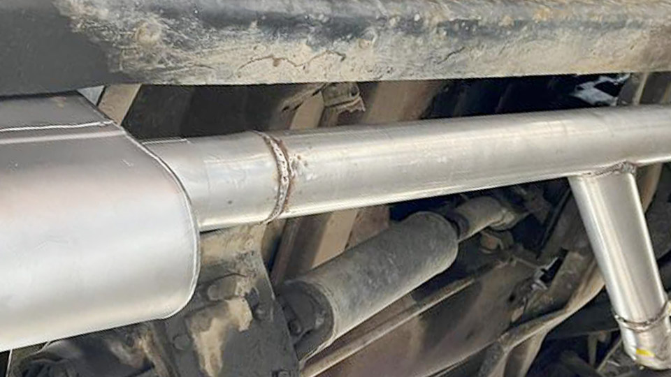
Image by welderamazing
Why Weld Bead Size Matters in Practice
Bead size determines load-bearing capacity in structural work, corrosion resistance in pressure vessels, and distortion control in fabrication. A bead that is too narrow lacks fusion; one that is too wide wastes time, filler, and risks defects like undercut or cracking.
Charts translate material thickness, joint type, and position into actionable settings while accounting for variables like shielding gas and technique.
Understanding Weld Bead Geometry
Key Dimensions and Measurements
- Bead Width: Distance across the face of the weld.
- Bead Height/Reinforcement: Convexity above the base metal surface.
- Penetration Depth: How far the weld fuses into the base material.
- Leg Length (Fillet Welds): Distance from the root to the toe along each plate (standard sizing method).
- Throat Thickness: Shortest distance through the weld cross-section (theoretical throat ≈ 0.707 × leg length for equal-leg mitre fillets).
For fillet welds, leg length is the primary specification. A 1/4″ leg fillet has a theoretical throat of approximately 0.177″. Inspectors use fillet gauges to verify leg size on both sides.
Ideal Bead Profiles by Process
MIG beads should show flat to slightly convex profiles with good toe tie-in. TIG beads on steel are often slightly convex with precise control. Stick (SMAW) beads vary by electrode but aim for consistent width of 2–3 times the core wire diameter in many positions.
MIG Welding Bead Size Control and Charts
MIG (GMAW) bead size is governed primarily by wire feed speed (WFS/amperage), voltage, travel speed, and gas.
Core Parameter Relationships in MIG
- Wire Feed Speed (Amperage): Controls deposition rate and penetration. Higher WFS increases heat and bead size.
- Voltage: Primarily controls arc length, bead width, and height. Higher voltage widens and flattens the bead.
- Travel Speed: Faster speed narrows the bead and reduces penetration; slower speed widens it and risks excess reinforcement.
Approximate MIG Settings for Mild Steel (Short-Circuit/Spray Transfer, 75/25 Ar/CO2)
Use these as starting points and adjust on scrap. Rule of thumb: 1 amp per 0.001″ of steel thickness.
- 16 ga (0.060″): 0.030″ wire, 16–18V, 140–180 IPM WFS (~80–110A), travel ~10–15 IPM for ~1/8″ wide bead.
- 14 ga (0.075″): 0.030″ wire, 17–19V, 180–220 IPM (~100–130A).
- 1/8″ (0.125″): 0.030–0.035″ wire, 18–20V, 220–280 IPM (~130–180A) for ~1/4–5/16″ bead width.
- 3/16″: 0.035″ wire, 19–22V, 240–320 IPM (~180–220A).
- 1/4″: 0.035–0.045″ wire, target ~250A, higher voltage for spray transfer.
For .035″ wire at 125A example: ~200 IPM WFS. Voltage fine-tuning yields stable arc without stubbing or burn-back.
Bead Diagnosis and Adjustment Table (MIG)
- Narrow/convex, poor tie-in: Increase voltage or slow travel; check low amps.
- Wide/flat, excessive spatter or burn-through: Decrease voltage or WFS; increase travel speed.
- Ropy/convex: Low voltage or fast travel.
- Turbulent pool, undercut: High voltage.
TIG Welding Bead Size Control
TIG (GTAW) offers superior control through amperage, travel speed, torch angle, and filler addition.
TIG Parameter Effects on Bead Size
Amperage sets puddle size and penetration (≈1 amp per 0.001″ mild steel). Travel speed and filler rod dipping control width and reinforcement. Torch angle (10–15° push) and arc length (≈ electrode diameter) are critical.
Typical TIG Amperage Guidelines (Mild Steel, DCEN)
- 0.040–1/16″: 20–50A, 1/16″ tungsten/filler, bead width ~1/8–3/16″.
- 1/8″: 60–100A for butt/fillet, adjust for position.
- 1/4″: 120–180A, multiple passes or weave for wider beads.
Aluminum requires AC and higher amperage (20–25% more). Stainless needs lower settings due to poor heat dissipation. Weaving or pulsing widens beads without excessive heat input.
Stick Welding (SMAW) Bead Size Guidelines
Electrode diameter and amperage dictate bead size. Maintain bead width ≈ 2–3× core diameter for many electrodes.
Common Stick Amperage Ranges
- 3/32″ E6013/7018: 40–80A for thin material.
- 1/8″: 75–125A typical.
- 5/32″: 110–180A.
Vertical-up: Lower amperage + weave to control puddle. Flat: Higher settings for faster travel and wider beads.
Factors Affecting Bead Size Across Processes
Heat Input and Travel Speed
Heat input (kJ/in) = (60 × Amps × Volts) / Travel Speed (IPM). Higher heat widens beads but risks distortion. Optimal travel balances penetration and profile.
Joint Design and Position
Butt joints need good penetration; fillets emphasize leg length. Overhead requires smaller beads and faster travel. Vertical demands puddle control techniques.
Material and Shielding Gas
Aluminum: Larger beads due to conductivity. Stainless: Tighter control to avoid sensitization. Gas mixtures (e.g., higher argon) stabilize arcs and influence width.
Technique Variables
- Electrode/torch angle.
- Arc length/stickout.
- Weave vs. stringer beads.
- Filler addition rate in TIG.
Selecting and Measuring Desired Bead Size
For Structural Fillets
Match leg size to thinnest member (common rule of thumb). AWS D1.1 provides minimum sizes based on thickness. Use gauges for verification.
Multi-Pass Strategy
Large beads or thick sections: Build with stringers or controlled weaves. Root pass: Smaller/narrower for fusion. Cap passes: Wider for coverage and appearance.
Calculating Requirements
For a required throat of 3mm on a mitre fillet: Leg length ≈ 4.24mm. Adjust settings to achieve consistent geometry.
Advanced Bead Size Optimization
Pulsed MIG or TIG reduces heat input while maintaining bead size. Synergic machines simplify settings but still require bead inspection. Monitor for defects: Lack of fusion (narrow/convex), undercut (high voltage/fast travel), porosity (gas issues).
Test settings on scrap matching your exact material, thickness, and position. Record successful parameters for repeatability.
Real-World Application Insight
Effective weld bead size selection comes down to balancing deposition, heat input, and joint demands for the required mechanical properties.
Professionals evaluate bead geometry against code or performance needs—penetration for strength, controlled reinforcement for fatigue resistance—then fine-tune one variable at a time while observing the puddle.
A pro-level insight: In critical applications, target a width-to-depth ratio around 1.5:1 to 2:1 to minimize centerline cracking risk while ensuring fusion. This geometry, combined with proper interpass temperature control, delivers welds that pass both visual and NDT inspection consistently.
FAQs
What determines weld bead width in MIG welding?
Voltage is the primary control—higher voltage lengthens the arc and widens the bead. Balance with WFS and travel speed for proper profile and tie-in.
How do I calculate fillet weld throat from leg size?
For a standard mitre fillet, theoretical throat = leg length × 0.707. Always verify with gauges on the actual weld.
Does travel speed affect bead size more than amperage?
It has a major influence on final width and reinforcement. Excessive speed creates narrow, ropey beads with poor fusion; too slow causes wide, flat beads with excess heat.
What is a good starting bead width for 1/8″ mild steel?
Aim for 1/4–5/16″ width with good penetration and toe tie-in. Adjust parameters based on process and joint type.