Accurately measuring a fillet weld is essential for verifying weld strength, meeting fabrication specifications, and passing quality inspections. Understanding how to measure a fillet weld helps welders, inspectors, and fabricators confirm that the weld provides the required load-bearing capacity without excessive weld metal or unnecessary production costs.
Incorrect fillet weld measurements can lead to under-sized welds that compromise structural integrity or over-sized welds that increase heat input, distortion, material consumption, and rework.
Whether you’re working from engineering drawings, welding procedure specifications (WPS), or inspection requirements, knowing the correct measurement method is critical for consistent results.
By understanding leg size, throat dimensions, and the proper use of fillet weld gauges, you can evaluate weld quality with greater confidence and ensure compliance with project requirements and industry standards.
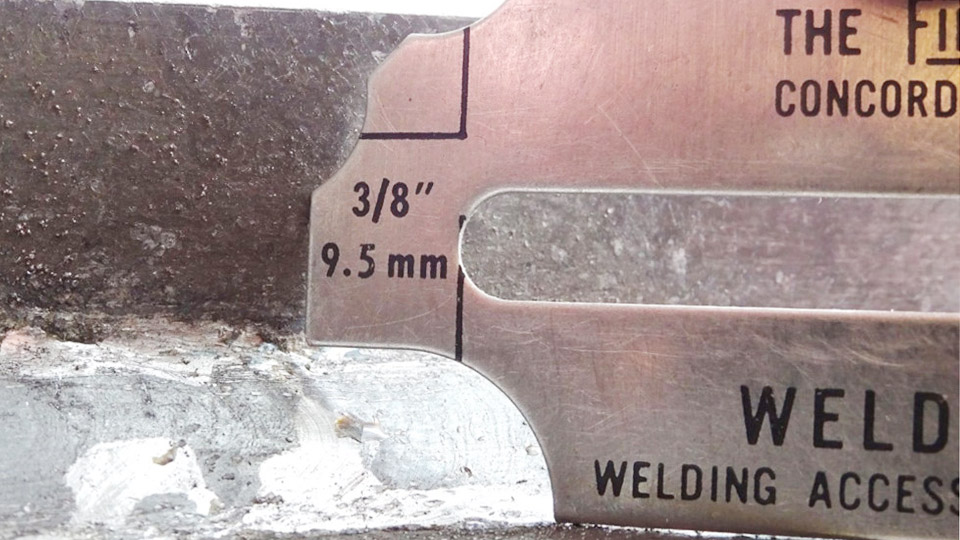
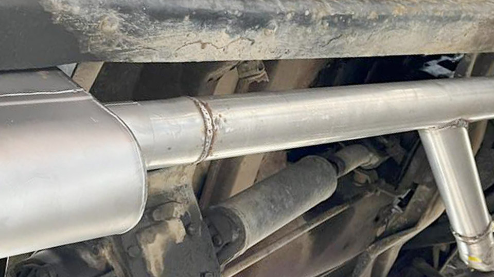
Image by in/karstenmadsenoptiweld
Understanding Fillet Weld Geometry and Sizing Basics
Fillet welds form a triangular cross-section joining perpendicular or angled surfaces, typically in T-joints, lap joints, or corner joints. The geometry defines strength calculations and inspection criteria.
Key Dimensions: Leg Length vs. Theoretical Throat
The leg length is the distance from the root (intersection of the two base metals) to the toe along each fusion face. For equal-legged fillets, inspectors measure the longest isosceles right triangle that fits inside the weld profile.
The theoretical throat is the shortest distance from the root to the hypotenuse of that triangle, equaling leg size × 0.707 (or approximately 70.7% of the leg). This dimension governs strength in shear-loaded joints.
Actual throat measures from root to the weld face, varying with convexity or concavity. For convex welds, leg length usually determines acceptance; for concave welds, the theoretical throat often controls.
How Weld Profile Affects Measurement
Convex profiles bulge outward, increasing leg measurements but potentially adding unnecessary material. Concave profiles dip inward, reducing effective throat even if legs appear adequate. Flat faces provide the ideal isosceles reference.
Standards like AWS D1.1 permit slight convexity or concavity but limit excessive deviations to avoid stress concentrations or reduced throat. Measure at multiple points along the weld length, as size can vary due to technique, travel speed, or heat input.
Tools for Measuring Fillet Welds
Accurate tools and proper technique minimize parallax errors and ensure repeatable results.
Standard Fillet Weld Gauges
The most common tool is the fillet weld gauge set, featuring templates for convex/flat and concave profiles. Place the gauge so one edge contacts the base metal while the other aligns with the weld toe. For convex welds, the gauge checks leg size directly. For concave, it verifies the minimum theoretical throat.
Multi-purpose gauges (e.g., bridge cam) also measure undercut, reinforcement, and angles. Calibrate or replace worn gauges regularly, as edge wear introduces errors of 1/32 inch or more.
Digital and Precision Alternatives
Digital fillet gauges or calipers with depth probes offer higher resolution for critical applications. Use them for throat measurements by probing from root to face, or for skewed joints where standard gauges fail. Laser scanners or CMMs provide 3D profiling in high-precision shops but are overkill for most fieldwork.
When to Use Other Inspection Methods
Visual testing (VT) precedes gauge use. For code work, supplement with magnetic particle or ultrasonic testing if subsurface fusion is questioned. Never rely solely on one measurement point—sample at least every 12 inches or at suspected low spots.
Step-by-Step: How to Measure a Fillet Weld Accurately
Execute these steps for consistent results on production or test welds.
- Clean the weld surface of slag, spatter, and oxidation to expose true toes and face.
- Identify the joint type and specified size from drawings (e.g., 1/4″ leg).
- Select the appropriate gauge side (convex or concave).
- Position the gauge perpendicular to the weld axis, flush against one base metal.
- Slide or rotate until the gauge contacts the toe without gap on the reference leg.
- Read the size at the point of contact. For both legs in unequal fillets, measure the smaller one as governing in many cases.
- Check throat on concave sections by using the dedicated template.
- Record minimum, maximum, and average values across the length. Note any convexity exceeding limits.
Repeat on the opposite leg and multiple cross-sections. For long welds, prioritize ends and starts where inconsistencies are common.
Standards and Acceptance Criteria for Fillet Weld Size
Codes dictate minimum sizes, tolerances, and profiles to ensure structural integrity.
AWS D1.1 Minimum Sizes and Tolerances
AWS D1.1 Table 7.7 (or equivalent) sets minimum leg sizes based on thicker part joined:
- Up to 1/4″ thick: 1/8″
- Over 1/4″ to 1/2″: 3/16″
- Over 1/2″ to 3/4″: 1/4″
- Over 3/4″: 5/16″
Single continuous fillets may underrun by 1/16″ at isolated points, but the average must meet or exceed the specified size. Convexity is limited (e.g., 0.07 × face width + 1/16″). Undersize legs are rejectable; throat reduction due to concavity can also fail the weld.
ISO and Other International Approaches
ISO standards often emphasize effective throat (denoted with “a” in symbols) rather than leg (“z”). This allows engineers to specify based on calculated strength needs. Conversion remains leg ≈ throat / 0.707.
Compare requirements project-by-project—European codes may be stricter on throat for fatigue-loaded structures.
Calculating Effective Strength from Measurements
Strength calculations use effective throat. For a 1/4″ leg equal fillet (assuming 70 ksi electrode), allowable shear load per inch approximates 0.707 × leg × allowable stress. Adjust for penetration in processes like SAW, where deeper fusion permits smaller nominal sizes.
Always verify against the specific code edition and engineering drawings.
Common Measurement Challenges and Real-World Decisions
Unequal Legs and Skewed Joints
In non-90° joints, legs differ. Measure each independently and use the effective throat or consult joint-specific gauges. The governing dimension is usually the one producing the smallest throat area.
Convexity, Concavity, and Over/Undersize Trade-offs
Excess convexity wastes filler metal and may concentrate stress at toes. Deep concavity reduces throat below specification even with full leg length. In practice, aim for flat to slight convex profiles for balanced productivity and acceptance.
If a weld measures slightly undersize on leg but exceeds throat requirements due to penetration, some codes allow engineering approval via procedure qualification. Document such cases thoroughly.
Multi-Pass Fillets and Layer Effects
Larger fillets require multiple passes. Measure the final profile, but ensure interpass fusion. Individual bead sizes affect overall leg development—monitor root pass for adequate penetration before building up.
Material Thickness and Heat Input Considerations
Minimum sizes prevent cracking in thicker materials due to rapid cooling. For thin sheets (<1/4″), avoid oversizing that causes burn-through or distortion. Adjust amperage, travel speed, and technique accordingly while verifying final measurements.
Advanced Techniques: Beyond Basic Gauging
Accounting for Penetration in Sizing
Certain processes (e.g., submerged arc) provide additional throat credit. AISC and others recognize this, allowing reduced leg sizes while maintaining effective throat. Qualify procedures with macros or sectioning to quantify actual penetration.
Digital Documentation and Statistical Process Control
For shops, integrate measurements into quality software. Track variation across shifts or machines to refine parameters. Statistical analysis of leg/throat data predicts process capability (CpK) for consistent compliance.
Destructive Verification for Critical Applications
Sample sectioning and polishing reveal true throat and fusion. Use this sparingly to validate non-destructive methods or resolve disputes.
Practical Applications in Different Welding Scenarios
Structural Steel: Strict AWS adherence; leg size primary. Measure before painting or coating.
Pipe and Pressure Vessels: ASME codes may reference similar fillet rules but add volumetric NDT. Focus on root fusion in socket welds.
Repair and Maintenance: Match existing weld profiles. Measure original size and duplicate throat strength, considering base metal condition.
Aluminum and Non-Ferrous: AWS D1.2 tolerances differ slightly; concavity more penalizing due to material properties.
In all cases, measurements inform decisions on rework versus acceptance.
Decision-Making Summary for Reliable Fillet Welds
Accurate fillet weld measurement combines geometry knowledge, proper tools, and code-specific rules to balance strength, cost, and quality. Prioritize throat dimension for load calculations while verifying legs for visual and minimum size compliance. Select tools based on joint complexity and production volume—gauges for speed, digital for precision.
In high-performance applications, treat fillet sizing as an optimization problem. Qualify procedures that leverage actual penetration and controlled profiles to reduce weld volume by 20-50% without sacrificing strength, directly lowering labor, distortion, and material costs while exceeding minimum code requirements.
FAQ
What is the difference between leg size and throat size in a fillet weld?
Leg size measures along the base metal faces to the toe. Throat size (theoretical) is the perpendicular distance from root to the face hypotenuse, approximately 0.707 × leg for equal legs. Codes may accept based on one or the other depending on profile and specification.
Can a fillet weld be undersize in some areas and still pass inspection?
Yes, under AWS D1.1, isolated underrun of up to 1/16″ is permitted for continuous welds, provided the weld meets average size and no continuous undersize segments violate length rules. Always check the full criteria and project specs.
How do you measure a concave fillet weld?
Use the concave side of the fillet gauge to check the theoretical throat against the minimum required. The gauge simulates the isosceles triangle; ensure the weld face clears the gauge notch without excessive gap.
What tools are best for measuring fillet welds in the field?
Standard fillet weld gauge sets are fast and sufficient for most work. Supplement with calipers for throat depth or bridge cam gauges for additional features like undercut. Keep tools clean and verify against known standards periodically.