Building a durable trailer starts with a properly engineered frame, and knowing how to build a trailer frame is essential for achieving the strength, stability, and load capacity your project requires.
Every decision—from material selection and frame layout to joint preparation and weld sequence—directly affects structural integrity, alignment, and long-term performance.
Poor weld penetration, heat distortion, or incorrect crossmember placement can lead to premature fatigue, failed inspections, costly rework, or even unsafe towing conditions.
Whether you’re fabricating a utility, equipment, or custom trailer, understanding the welding principles behind a strong frame helps prevent common fabrication mistakes and improves overall reliability.
I’ll explain the practical techniques and structural considerations that experienced fabricators use to produce a trailer frame capable of handling real-world loads with confidence.
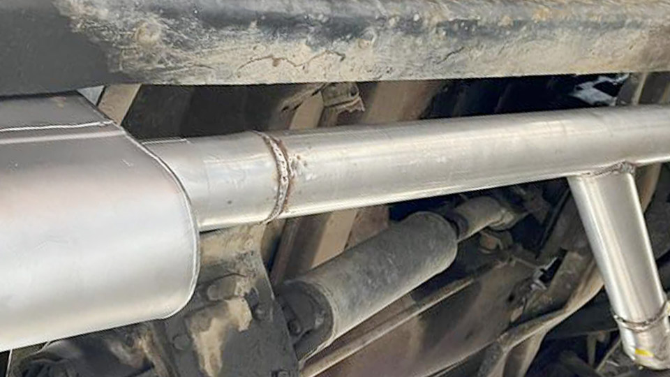
Image by theshed
Material Selection and Frame Design Fundamentals
Steel Types and Grades for Structural Integrity
A36 mild steel remains the most common and weldable choice for trailer frames due to its balance of strength, cost, and availability. Yield strength around 36,000 psi supports typical bending and shear loads when sized appropriately.
For higher-performance builds, A572 Grade 50 offers improved yield (50,000 psi) with minimal weight penalty, ideal for longer spans or heavier capacities.
Rectangular tubing (e.g., 2x4x1/8″ or 2x3x3/16″) provides excellent torsional resistance and clean joint surfaces for cross members. C-channel excels for perimeter rails and outriggers because it allows easy through-bolting for decking without crushing.
I-beams suit longer main rails (>16 ft) where vertical stiffness dominates bending loads. Avoid over-relying on thin wall tubing (<11 gauge) for main beams in capacities above 3,500 lbs without generous gusseting.
Determining Beam Sizing and Load Capacity
Calculate required section modulus based on expected loads. For a simple uniformly distributed load, maximum bending moment M = (w * L²)/8, where w is load per unit length and L is span. Compare resulting stress (σ = M * c / I) against material yield with a safety factor of 2–3 for dynamic road use.
For a typical 7×12 single-axle utility trailer targeting 5,000–7,000 lb capacity:
- Main rails: 2x4x1/4″ or 2x6x3/16″ rectangular tube.
- Cross members: 2x3x1/8″ on 16–24″ centers.
- Tongue: 2x5x1/4″ or dual 2×3 tubing with gussets.
Cross members on 16″ centers distribute deck loads effectively for concentrated items like equipment. Wider trailers (>8 ft) demand stronger outriggers or additional perimeter rails to prevent side flex. Always verify axle placement for proper tongue weight (10–15% of GVWR).
Corrosion Protection and Preparation
Hot-dip galvanizing or high-build epoxy primer followed by enamel topcoat outperforms bare or lightly painted frames in road salt environments. Grind all mill scale and rust before assembly. Seal tube ends with welded caps or plugs to prevent internal corrosion. Pre-drill mounting holes for axles, lights, and decking while pieces are accessible on the setup jig.
Workshop Setup and Precise Frame Assembly
Creating a True Reference Plane
Garage floors are rarely flat enough (±0.5″ deviation common). Establish a reliable build plane using two straight steel beams arranged in a broad V or parallel with cross supports at three points (three points define a plane). Elevate on stable blocks or sawhorses. This prevents built-in twist or bow that propagates through the entire structure.
Fixturing for Squareness and Alignment
Use plywood sheets (factory edges are reliably square) or large carpenter squares combined with pipe clamps and ratchet straps to hold main rails parallel and perpendicular. Fixture blocks or angle plates clamped to the reference beams maintain verticality.
Tack extensively before full welding—multiple small tacks distributed around each joint minimize pull. Measure diagonals repeatedly (equal diagonals confirm squareness).
Drill holes for suspension mounts, wiring, and deck fasteners prior to full assembly. This avoids awkward post-weld drilling on a heavy frame.
Welding Techniques for Trailer Frames
Process Selection and Parameters
MIG (GMAW) with ER70S-6 wire (0.035″) and 75/25 Ar/CO2 shielding offers speed, clean beads, and good penetration for most trailer work. Settings: 18–22V, 180–250A depending on thickness. For thicker sections or outdoor conditions, FCAW (flux-cored) self-shielded wire performs well.
Stick (SMAW) with 7018 rods (3/32″ or 1/8″) suits field repairs or thicker material but requires more skill to control heat input.
TIG excels for aluminum frames but is slower for steel structural work.
Joint Preparation and Weld Types
Bevel edges for full penetration butt joints on main rail splices. Clean to bright metal. Fillet welds dominate frame corners and cross member attachments—aim for leg size matching thinner material thickness (e.g., 1/4″ fillet on 1/4″ plate).
Lap joints work for gussets but require welds on both sides. Avoid excessive weld volume on top/bottom flanges of main beams where bending stress peaks.
Distortion Control and Sequencing
Heat input causes expansion and contraction. Use a balanced “star” or back-step pattern: weld short segments, alternate sides and ends, allowing cooling between passes. Tack all major intersections first, check alignment, then progress outward from center.
For channel or tube, weld opposite sides alternately. Gussets in corners reduce racking; weld them with short, intermittent beads.
Post-weld, stress-relieve critical areas if possible, though natural cooling with balanced sequencing usually suffices for mild steel frames.
Key Structural Elements and Reinforcement
Main Rails and Cross Members
Main rails carry primary bending. Space cross members to limit deck deflection under point loads. For torsion resistance, box sections or added triangular gussets at intersections outperform open profiles alone. Outriggers extending the bed require robust attachment—full perimeter welds plus gussets prevent fatigue cracks.
Tongue and Hitch Integration
The tongue experiences high combined bending, shear, and torque. Use heavier section (e.g., 2x5x1/4″) or dual tubes converging to the coupler. Profile joints to fit tightly.
Add diagonal braces from tongue to main rails forming a strong A or V configuration. Weld the coupler after removing paint and ensuring full penetration. Balance welding to avoid downward sag.
Axle Mounting and Suspension Integration
Mount axles via spring perches or torsion brackets welded to reinforced cross members or dedicated plates. Temporary bolt the axle in place for alignment, tack brackets, remove axle, then complete welds.
Avoid welding directly on main beam faces in high-stress zones; use fish plates or doublers if modifications are needed. Ensure camber and toe alignment post-welding.
Gussets, Bracing, and Perimeter Reinforcement
Triangular gussets at all major corners and intersections dramatically increase rigidity with minimal weight. Place them on both top and bottom where practical.
For high-capacity or off-road frames, consider truss elements or additional longitudinal stiffeners. Perimeter rails (if not formed by main beams) tie the structure together and support side loads.
Advanced Considerations for Performance and Durability
Weight Distribution and Towing Dynamics
Target 10–15% tongue weight for stable towing. Frame design influences this—longer tongues or forward axle placement shifts balance. Account for dynamic loads: road impacts multiply static forces. Overbuild slightly rather than calculate to exact minimum.
Deck and Accessory Integration
Pre-plan mounting for fenders, lights, winches, and ramps. Channel cross members simplify bolting plywood or steel decking. Ensure drainage to prevent water trapping. For aluminum decks on steel frames, use isolation materials to avoid galvanic corrosion.
Inspection and Testing
After welding and cooling, check for cracks with dye penetrant or magnetic particle inspection on critical joints. Load test incrementally (static weights then road trials). Monitor for flex or unusual noises. Repaint any heat-affected zones.
Real-World Application Insights
Successful trailer frames balance strength, weight, and manufacturability. Prioritize full-penetration welds and balanced heat input over massive over-welding. Choose materials that simplify fabrication while meeting calculated loads.
A well-executed frame using 2×4 tubing with strategic gussets and proper sequencing will outperform a heavier but poorly assembled one under repeated road abuse.
Pro-level insight: Treat the frame as a system where suspension mounting points and tongue transitions often dictate longevity more than raw beam size—focus reinforcement there for maximum return on effort.
FAQ
What gauge steel is best for a DIY trailer frame?
For most 5,000 lb capacity utility trailers, 11–13 gauge (1/8″–3/16″) rectangular tubing works well for rails, with heavier 1/4″ in high-stress areas like the tongue. Match thickness to calculated bending stress and add gussets liberally.
Should I use MIG or stick welding for trailer frames?
MIG with ER70S-6 is preferred for speed, cleanliness, and control on thinner sections. Stick (7018) is viable for thicker material or outdoor work but demands better heat management to avoid distortion.
How do I prevent warping when welding a trailer frame?
Tack thoroughly, use balanced star-pattern welding, alternate sides, employ short beads with cooling intervals, and build on a true flat reference plane. Clamping during tacking is essential.
What is the ideal spacing for cross members?
16–24 inches on center balances load distribution and deck support for most applications. Closer spacing (12–16″) for heavy point loads like machinery.