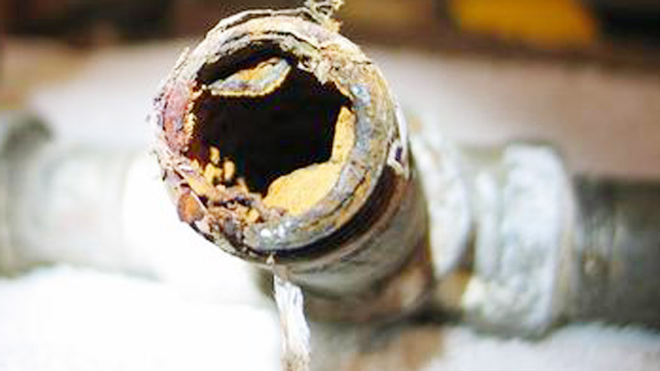
Welding thin sheet metal—typically 24 gauge to 16 gauge (0.5 mm to 1.6 mm)—presents immediate frustration for many fabricators. A slight excess in heat input creates burn-through holes, while insufficient fusion leaves weak joints that fail under vibration or load.
This is especially critical for automotive body panels, ductwork, custom fabrication, and repair work where structural integrity and appearance both matter.
Mastering how to weld thin sheet metal requires precise control of heat input, material preparation, process selection, and technique to achieve consistent, distortion-free results without compromising strength.
Image by r/Welding
Understanding Material Properties and Common Failure Modes
Thin sheet metal conducts heat poorly and has minimal thermal mass, so localized heating causes rapid expansion followed by contraction during cooling. This leads to warping, buckling, or cracking, particularly in large flat panels or areas with existing rust or coatings.
Mild steel, stainless, and aluminum each behave differently. Mild steel tolerates moderate heat but distorts easily. Stainless retains heat longer, increasing burn-through risk. Aluminum conducts heat rapidly and oxidizes quickly, demanding different parameters and filler choices.
Key failure points include excessive amperage/voltage causing melt-through, poor fit-up creating gaps that amplify heat concentration, and continuous beads building heat without dissipation.
Addressing these begins with accurate thickness identification—use a gauge or micrometer rather than visual estimation—and matching processes to the specific alloy and joint configuration.
Thickness Ranges and Process Suitability
- 24–20 gauge (0.5–0.9 mm): Best suited for TIG or pulsed MIG with very low settings. Avoid standard short-circuit MIG.
- 18–16 gauge (1.0–1.6 mm): MIG becomes viable with .023″–.030″ wire; TIG offers superior control.
- Material-specific adjustments: Reduce settings 10–20% for stainless versus mild steel due to lower thermal conductivity.
Selecting the Optimal Welding Process
Process choice determines success more than welder skill alone. MIG excels in speed for production or larger repairs, while TIG provides precision for visible or high-quality work.
MIG Welding: Speed with Controlled Heat
MIG (GMAW) in short-circuit transfer mode works well for thin materials when properly configured. Use .023″ or .024″ solid wire for the lowest heat input. Thinner wire melts at lower amperage and allows faster travel speeds.
Shielding gas: 75% argon/25% CO2 (C25) provides good arc stability, reduced spatter, and lower heat than pure CO2. Flow rate: 15–20 CFH. Avoid flux-cored wire on very thin stock due to higher heat and slag.
Typical parameters for mild steel (adjust per machine and test welds):
- 24 gauge: 30–50 amps, 13–15 V, wire feed 130–160 ipm, travel 10–20 ipm.
- 18 gauge: 50–80 amps, 15–17 V, appropriate WFS for stable short-circuit.
- Stickout: Keep 3/8″–5/8″ maximum for control.
Push technique (forehand) helps direct heat forward and improves shielding. Use pulse or synergic machines if available for automatic heat management.
TIG Welding: Precision and Low Distortion
TIG (GTAW) is preferred for the thinnest sheets and cosmetic repairs. It allows independent control of heat via foot pedal and minimal filler addition.
Setup:
- Tungsten: 3/32″ or smaller (1.6 mm or less), ceriated or thoriated, sharpened to a fine point.
- Amperage: Rule of thumb ~1 amp per 0.001″ thickness. Start at 35–60 amps for 0.030″–0.060″ steel, using pulse (1–3 Hz, 10–30% duty cycle) for better control.
- Gas: Pure argon at 15–20 CFH.
- Filler: Match base metal; use 1/16″ or smaller rod. Avoid filler thicker than base material.
DCEN polarity for steel. Pull the torch at 10–15° angle. Add filler to the leading edge of the puddle to build bead without overheating the base.
TIG produces smaller, softer beads ideal for hammer-and-dolly work on auto panels.
Joint Design and Material Preparation
Proper preparation prevents most common defects. Clean surfaces thoroughly—remove rust, paint, oil, and mill scale with a dedicated grinder or chemical cleaner. Contaminants cause porosity and weak fusion.
Joint types:
- Butt joints: Preferred for flush appearance and to avoid moisture traps in repairs. Require tight fit-up with minimal gap (<0.5 mm).
- Lap joints: Easier alignment but higher heat concentration; use sparingly.
- Plug or spot welds: Excellent for panels where continuous seams are unnecessary.
Clamp pieces securely with copper backing bars or heat sinks where accessible. These absorb excess heat and support the puddle. Tack welds every 1–2 inches, alternating sides to balance shrinkage. Let cool between tacks.
Minimize gaps by precise cutting and fitting. For patches, cut slightly oversized and trim progressively for near-perfect contact.
Heat Management and Distortion Control Techniques
Distortion arises from uneven heating and cooling. Core strategies focus on minimizing total heat input while ensuring fusion.
Pulsing and stitch welding: Weld short segments (1/2″–1″) or use machine pulse settings, allowing cooling between. Skip around the joint rather than progressing sequentially.
Backstepping: Weld in short increments opposite the direction of progression. This counters shrinkage forces.
Clamping and fixturing: Use strong clamps, magnets, or temporary braces. Copper or aluminum backing dissipates heat effectively.
Travel speed: Maintain consistent, brisk speed—faster for thinner material—to limit dwell time. Aim for a small, controlled puddle.
For severe warping post-weld, use hammer and dolly on supported areas while warm, or heat-shrink techniques with a rosebud torch and quenching (with caution on high-carbon steels).
Advanced Techniques for Specific Applications
Automotive Body Panel Repair
Butt weld patches where possible. Use MIG with .023″ wire and C25 gas for speed, or TIG for minimal filler and easier finishing. Tack densely, then fill with overlapping stitches. Silicon bronze wire (MIG brazing) reduces heat further and produces softer beads for grinding.
Stainless and Aluminum Thin Sheet
Stainless: Lower amps than mild steel, back purge if possible for full penetration without oxidation. Aluminum: AC TIG with pure argon, higher travel speed due to conductivity. Use 4043 or 4943 filler for aluminum.
Multi-Pass Considerations
Rarely needed on thin sheet. If required, keep passes extremely light and interpass temperature low (<150°F/65°C).
Post-Weld Processing and Quality Assurance
Grind welds flush carefully—use thin cutting wheels or flap discs at low pressure to avoid thinning the base metal further. For bodywork, planish with hammer and dolly for strength and flatness.
Inspect for cracks, porosity, or undercut. Test joints under load if structural. Proper parameters yield welds stronger than the base material in many cases.
Equipment and Consumable Recommendations
- MIG: Machines with good low-end control, .023″–.030″ wire.
- TIG: Inverter with pulse and foot pedal.
- Accessories: Gas lens for better shielding, tungsten sharpener, dedicated clamps.
Decision-Making Summary for Reliable Results
Successful thin sheet welding hinges on deliberate heat control, tight fit-up, and process matching to material and joint. Test settings on scrap of identical thickness and alloy before production welds. Prioritize minimal heat input through thin wire, pulsing, stitching, and backing where feasible.
This approach delivers strong, low-distortion joints suitable for demanding applications like restoration or fabrication.
On critical thin stainless or aluminum components, combine pulsed TIG with copper backing and real-time temperature monitoring (e.g., temp sticks or IR) to stay below distortion thresholds while achieving full penetration—elevating results beyond standard practice.
FAQ
What wire size is best for MIG welding thin sheet metal?
Use .023″ or .024″ solid wire for the lowest heat input and best control on material under 1.2 mm. Larger diameters require higher settings that increase burn-through risk.
How do I prevent warping when welding auto body panels?
Tack frequently while alternating sides, use short stitch welds with cooling intervals, employ copper backing, and maintain fast travel speed. Avoid long continuous beads.
Is TIG or MIG better for very thin sheet metal under 0.8 mm?
TIG provides superior control and lower overall heat for the thinnest gauges. MIG works with pulse or precise short-circuit settings but demands more operator skill to avoid defects.
What shielding gas should I use for thin mild steel sheet?
75/25 argon/CO2 mix offers excellent arc stability, reduced spatter, and lower heat input compared to pure CO2.