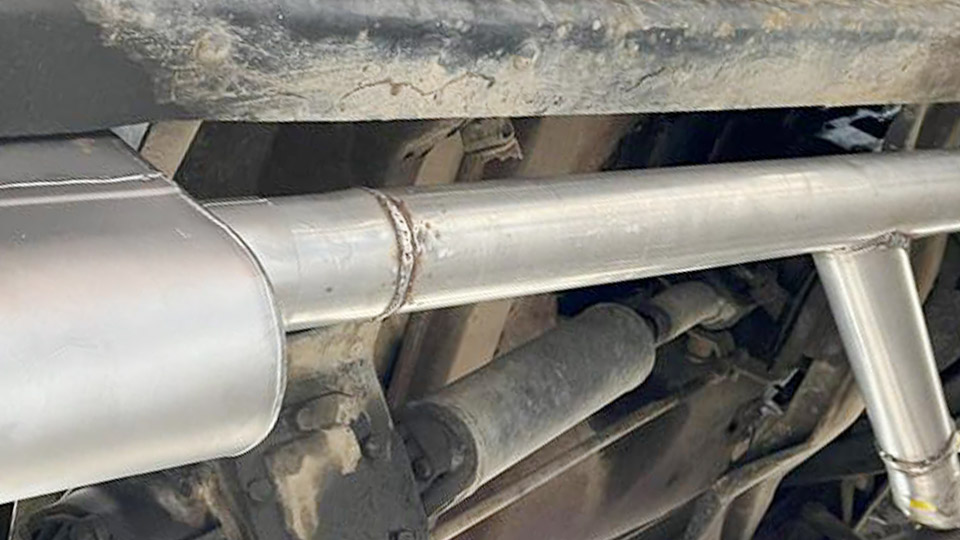
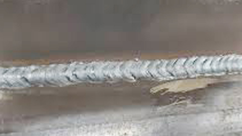
Welders frequently face a critical decision after completing a joint: how to verify internal integrity without destroying the work. A porosity cluster or tight lack-of-fusion crack can compromise structural performance, yet choosing the wrong volumetric non-destructive testing (NDT) method leads to missed defects, unnecessary repairs, or inflated costs.
Radiographic Testing vs Ultrasonic Testing (RT vs UT) represents one of the most important comparisons in weld quality assurance. Both detect subsurface flaws in welds, but their physics, capabilities, and practical trade-offs differ sharply, directly affecting decisions on pipelines, pressure vessels, structural steel, and custom fabrication.
This comparison equips DIY enthusiasts, students, hobbyists, and professionals with the technical details needed to select the optimal method based on material, defect risks, access, code requirements, and project constraints.
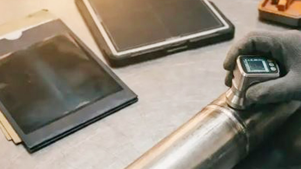
Image by vareximaging
Principles of Radiographic Testing (RT) in Weld Inspection
Radiation Physics and Image Formation
RT uses X-rays (from tubes) or gamma rays (from isotopes like Ir-192 or Co-60) that penetrate the weld. Denser material absorbs more radiation; voids, porosity, or inclusions absorb less, creating darker areas on film or digital detectors. The result is a 2D projection of density variations through the entire thickness.
Key parameters include source-to-film distance (SFD), tube voltage (kV), exposure time, and image quality indicators (IQIs or penetrameters) to verify sensitivity (e.g., 2-2T quality level per ASME Section V Article 2 or ISO 17636). For steel welds, lower kV improves contrast for thinner sections, while gamma sources suit thicker or field work.
Common Weld Defects Detected by RT
RT excels at volumetric defects:
- Porosity: Round or elongated dark spots; clustered or scattered porosity shows clearly as density variations.
- Slag inclusions: Irregular dark areas with defined edges.
- Incomplete penetration: Distinct dark lines at the root.
- Tungsten inclusions: Sharp, high-contrast spots (in GTAW).
It provides a permanent record ideal for traceability in code work.
Limitations arise with planar defects. Tight cracks or lack-of-fusion parallel to the beam produce minimal contrast unless favorably oriented, often going undetected.
Principles of Ultrasonic Testing (UT) in Weld Inspection
Sound Wave Propagation and Reflection
UT sends high-frequency sound waves (typically 2–5 MHz for welds, up to 10+ MHz in advanced setups) into the material via a transducer. Reflections from interfaces (defects, backwall) return as echoes.
Time-of-flight and amplitude determine location, depth, and size. Shear waves (angle-beam, 45°/60°/70°) are standard for weld fusion faces.
Calibration uses Distance-Amplitude Correction (DAC) curves from side-drilled holes (SDH) in reference blocks to compensate for beam spread and attenuation. Modern phased array UT (PAUT) steers beams electronically for sectorial scans, improving coverage and imaging.
Defect Detection and Characterization in UT
UT is highly sensitive to planar defects:
- Cracks and lack-of-fusion (LOF): Strong reflectors when perpendicular to the beam; excellent for sidewall LOF.
- Lack of penetration: Clear root indications.
- Laminations: Parallel to surface.
It struggles more with small, rounded porosity (appears as point reflectors) and requires skilled interpretation. PAUT provides encoded C-scans or S-scans for better visualization and sizing (through-wall height).
Direct Comparison: RT vs UT for Weld Applications
Defect Detection Performance
Studies consistently show complementary strengths:
- RT superior for volumetric flaws (porosity, slag) due to clear 2D imaging.
- UT/PAUT superior for planar flaws (cracks, LOF), critical in fatigue-prone structures.
Probability of Detection (POD) data indicates UT often outperforms RT on cracks, while RT catches small volumetric indications better in some cases. Combined use (UT screening + RT confirmation) is common in critical applications.
Side-by-Side Technical Comparison Table:
| Aspect | Radiographic Testing (RT) | Ultrasonic Testing (UT/PAUT) |
|---|---|---|
| Principle | Radiation absorption/density variations | Acoustic reflection/time-of-flight |
| Best For | Volumetric (porosity, slag, inclusions) | Planar (cracks, LOF, laminations) |
| Permanent Record | Excellent (film/digital image) | Digital data/scans (less intuitive “picture”) |
| Access Required | Typically both sides | Often one side |
| Speed | Slower (setup, exposure, processing) | Faster (real-time, 3-10x in many cases) |
| Safety | Radiation hazards, exclusion zones | No radiation |
| Cost | Higher (equipment, personnel, downtime) | Lower |
| Operator Skill | Interpretation of images | Signal analysis and scanning technique |
| Thickness Suitability | Good for varied; geometry-dependent | Excellent for thick sections |
Practical Factors in Field and Shop Settings
Access and Geometry: UT shines on large structures or pipes with single-side access. RT needs line-of-sight and both sides, challenging for complex assemblies.
Production Volume: High-volume fabrication favors UT for minimal disruption. RT suits smaller batches needing visual proof.
Material Considerations: Both work on ferrous and many non-ferrous metals, but UT attenuation is higher in coarse-grained austenitic stainless or nickel alloys, sometimes favoring RT or advanced PAUT.
Code Compliance: ASME Section V, AWS D1.1, API 1104, and ISO standards accept both, with increasing allowance for UT/PAUT as RT alternatives, especially with performance demonstration.
When to Choose Radiographic Testing for Your Welds
Scenarios Favoring RT
- Projects requiring permanent visual records for regulatory or client acceptance (e.g., pressure vessels, aerospace).
- Primary concern is porosity or slag distribution in manual welding.
- Controlled shop environments where radiation safety is manageable.
- Verification of complete penetration in butt joints where 2D projection clarifies root conditions.
Technique Optimization for Welds
Select Class B techniques (ISO 17636) for critical work. Use appropriate sources: X-ray for thinner steel (<20-30 mm), gamma for thicker. Position IQIs on the weld side for sensitivity. Digital radiography (CR/DR) reduces processing time while maintaining records.
Avoid over-reliance on RT for fatigue-critical welds prone to cracks.
When to Choose Ultrasonic Testing for Your Welds
Scenarios Favoring UT/PAUT
- Field or on-site inspections with time or access constraints.
- Detection of planar defects in high-cycle fatigue or dynamic loading applications.
- Thick sections or materials where deep penetration is needed without radiation logistics.
- High-volume production needing immediate feedback for welder adjustments.
Calibration and Scanning Best Practices
Construct DAC/TCG curves using SDH references. For PAUT, use sectorial and linear scans from both sides of the weld. Apply transfer corrections for material variations. Encoder-equipped systems provide positional accuracy for sizing.
Focus scans on heat-affected zones and fusion lines at multiple angles.
Hybrid Approaches and Emerging Trends
Many critical welds use UT as primary screening (fast, safe) followed by targeted RT for characterization. Phased Array and TOFD enhance UT sizing accuracy, supporting fitness-for-service evaluations. Codes increasingly permit UT alternatives to RT with proper qualification.
Digital advancements in both methods improve archiving and analysis, but physics-based strengths remain.
Decision Framework for Welders and Inspectors
Evaluate:
- Dominant expected defects (volumetric → RT; planar → UT).
- Access and site constraints.
- Need for permanent image record.
- Budget, schedule, and safety.
- Applicable code acceptance criteria.
For most modern fabrication, UT/PAUT offers superior efficiency and crack detection. RT remains essential where visual documentation is mandated.
Wrapping Up
In high-stakes welding, the best choice aligns method physics with failure modes: prioritize crack-sensitive UT for dynamic loads and RT for volumetric documentation needs. Advanced PAUT continues closing gaps, enabling safer, faster, and more reliable weld verification across industries. This technical decision directly impacts joint performance, project timelines, and long-term integrity.
FAQ
Is Ultrasonic Testing a full replacement for Radiographic Testing in welds?
No single method is universal. UT often replaces RT for planar defects and speed, but RT provides unmatched porosity visualization and permanent 2D records. Many codes allow substitution with qualified procedures; hybrid use maximizes coverage.
Which method is better for detecting cracks in welds?
Ultrasonic Testing, particularly PAUT, due to strong reflections from planar surfaces. RT can miss tight cracks unless perfectly aligned with the beam.
How do costs compare between RT and UT for weld inspection?
UT is generally 3-10x faster and cheaper per weld (lower labor, no exclusion zones), though initial equipment varies. RT incurs higher ongoing costs from safety, setup, and processing.
What training is required for RT vs UT on welds?
Both require certified Level II/III personnel (ASNT, ISO 9712, etc.). RT emphasizes radiation safety and image interpretation; UT focuses on calibration, scanning, and signal analysis. PAUT adds specialized training.