Accurate weld inspection is essential because even small cracks can reduce structural integrity, shorten service life, and lead to costly failures if they go undetected. How Ultrasonic Testing Detects Cracks is a critical topic for welders, inspectors, and quality control professionals who need reliable non-destructive testing methods without damaging the workpiece.
By transmitting high-frequency sound waves into a weld, ultrasonic testing can identify internal discontinuities that visual inspection cannot reveal, helping prevent unexpected failures, unnecessary repairs, and rejected components.
Understanding how this process works also improves inspection planning, code compliance, and confidence in weld quality across industries such as construction, manufacturing, and pipeline fabrication.
I’ll explain the principles behind ultrasonic testing, how crack indications are interpreted, and the factors that influence inspection accuracy in real welding applications.
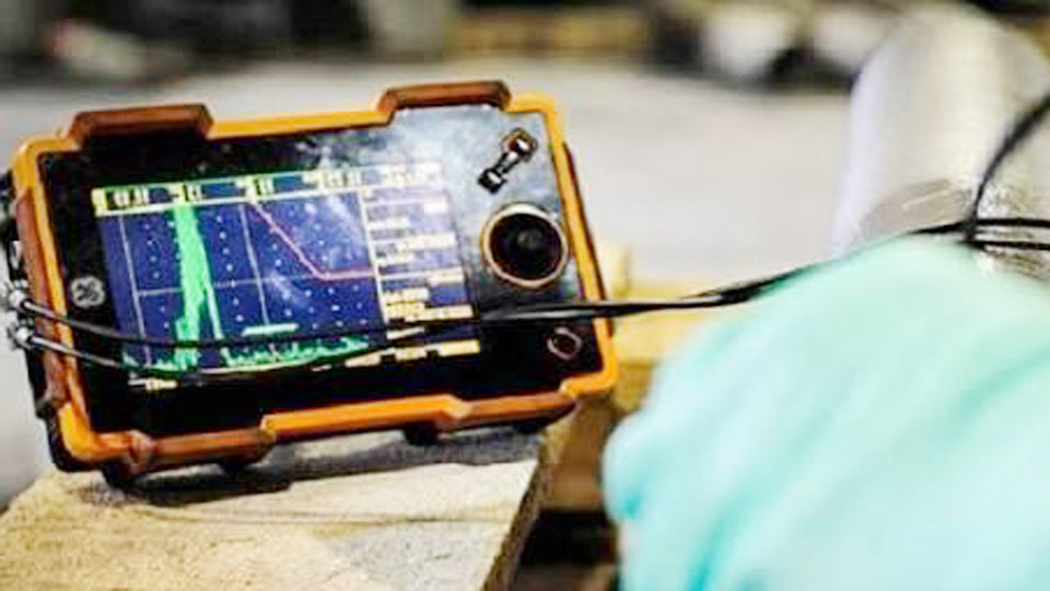
Image by laboratuar
Principles of Ultrasonic Wave Propagation in Welds
Ultrasonic testing (UT) relies on high-frequency sound waves, typically 2–5 MHz for weld inspection, introduced into the material via a piezoelectric transducer.
These waves travel through the base metal and weld metal until they encounter a boundary with differing acoustic impedance, such as a crack face, where part of the energy reflects back.
Longitudinal vs. Shear Wave Modes
Longitudinal (compression) waves vibrate parallel to the direction of propagation and suit straight-beam thickness measurements or detecting volumetric defects like porosity. Shear (transverse) waves, generated using angle-beam wedges (commonly 45°, 60°, or 70° refracted angles), vibrate perpendicular to propagation.
Shear waves excel at detecting planar defects like cracks because their shorter wavelength and mode conversion behavior produce stronger reflections from crack faces.
In practice, select the refracted angle based on weld preparation geometry. A 60° probe often provides optimal coverage for V-groove butt welds in plates 12–50 mm thick, balancing skip distance and sensitivity to both toe and root defects.
Reflection, Refraction, and Diffraction at Crack Interfaces
When a shear wave strikes a crack, the primary reflection returns to the probe. Tip diffraction from the crack ends generates weaker signals that allow accurate height sizing.
Surface-breaking cracks produce corner-trap reflections with high amplitude due to the double reflection off the crack face and back wall. Embedded cracks rely more on direct reflection and diffraction.
Material attenuation, grain structure in the weld, and surface condition affect signal strength. Coarse-grained welds (e.g., certain stainless or thick multipass carbon steel) scatter energy, requiring lower frequencies (around 2.25 MHz) or advanced techniques.
Equipment and Setup for Effective Crack Detection
Transducers and Wedges
Standard angle-beam transducers range from 2.25–5 MHz with crystal sizes of 8–25 mm. Smaller probes offer better resolution in tight spaces but less penetration.
Wedges made of plastic (e.g., Rexolite) introduce the wave at the desired angle via Snell’s Law refraction. Always verify the actual refracted angle on a calibration block, as wedge wear or temperature changes alter it.
Phased array ultrasonic testing (PAUT) uses multi-element probes (16–128 elements) to electronically steer and focus the beam, reducing the need for multiple wedges and improving coverage in a single pass.
Instruments and Display Modes
Modern flaw detectors display data in A-scan (amplitude vs. time), with options for B-scan (cross-sectional) and C-scan (plan view) in advanced systems. PAUT and Total Focusing Method (TFM) generate detailed images that simplify interpretation.
Time-of-Flight Diffraction (TOFD) employs separate transmitter and receiver probes to capture diffracted signals from crack tips, offering superior sizing accuracy independent of amplitude.
Calibration Procedures for Reliable Results
Calibration ensures accurate defect location, sizing, and evaluation. Perform it before each shift, after changes in setup, and verify periodically.
Range and Velocity Calibration
Use an IIW (International Institute of Welding) block or equivalent. For shear waves, set the range to cover at least 1.5 times the material thickness using known reflectors (e.g., 100 mm radius in the IIW block). Adjust velocity to match the material—typically 3.23 km/s for shear waves in carbon steel.
Sensitivity and DAC/TCG
Create a Distance Amplitude Correction (DAC) curve using side-drilled holes (SDH) of 1.5–3 mm diameter at various depths. Plot the peak amplitudes and connect them. This compensates for beam spreading and material attenuation. Time Corrected Gain (TCG) achieves similar compensation electronically.
Reference level is often set at 80% full screen height (FSH) on the reference reflector. Scanning sensitivity is typically +6 dB or as specified by the code (e.g., AWS D1.1 or ASME Section V).
Probe Index and Angle Verification
Mark the beam exit point (index) on the wedge and confirm the actual refracted angle. Misalignment here leads to plotting errors and missed defects.
Scanning Techniques for Different Crack Locations
Root Cracks
Root cracks emanate from the weld root or incomplete penetration. They produce strong corner-trap echoes. Scan from both sides using full skip to ensure the beam reflects off the root area. TOFD and TFM excel here due to clear tip diffraction signals for height measurement.
Sidewall and HAZ Cracks
These follow the fusion line or HAZ. Orientation often requires scanning from both sides of the weld with half and full skip paths. Signals may appear displaced if the crack is not perpendicular to the beam. Multiple angles (e.g., 45° and 70°) help confirm.
Toe Cracks
Surface-breaking toe cracks may require high-angle beams or surface wave techniques for detection, though they often combine with visual or penetrant testing. Full skip paths improve depth sizing.
Centerline Cracks
Embedded in the weld centerline, these demand careful plotting. Reflections can “skip” and appear elsewhere. Inspect from both sides and use multiple techniques (conventional + TOFD) for confirmation.
Interpreting Indications and Sizing Cracks
A-scan shows peaks: location from time-of-flight, amplitude indicates severity (after DAC correction), and signal shape helps characterize (crack signals are often sharp and jagged compared to rounded slag or porosity).
Sizing Methods:
- 6 dB Drop: For length, move the probe until the signal drops to half amplitude (-6 dB) from each end.
- Tip Diffraction: Measures height using the time difference between top and bottom diffracted signals. Highly accurate with TOFD/TFM.
- Amplitude Comparison: Relative to DAC curve for acceptance.
Plot indications on a weld cross-section sketch or use software for PAUT/TFM to visualize in 3D.
Advanced Techniques: PAUT, TOFD, and TFM
PAUT sweeps multiple angles electronically, ideal for complex geometries and reducing scan time. It improves detection of misoriented cracks.
TOFD provides excellent sizing for through-wall extent with minimal dependence on amplitude.
TFM (with Full Matrix Capture) focuses synthetically on every point, producing high-resolution images that reveal crack morphology, including branching into the HAZ.
These methods complement conventional UT, especially on critical welds where precise remaining life assessment matters.
Factors Affecting Detection Reliability
Surface condition must be smooth (typically <125 µin RMS); grind weld caps flush where possible. Couplant (gel or paste) ensures transmission—apply evenly and avoid air gaps.
Weld geometry, backing bars, and access limit scanning. Temperature affects velocity (correction factors apply above 50°C). Operator skill remains the largest variable; certified Level II or III technicians following written procedures minimize errors.
Material type influences choice: ferritic steels respond well; austenitic stainless requires special low-frequency or advanced techniques due to anisotropy.
Comparison with Other NDT Methods
UT outperforms radiography (RT) for planar cracks (tight cracks may not show sufficient contrast on film). RT excels at volumetric defects. UT is safer (no radiation), faster for many applications, and portable.
Magnetic particle and penetrant detect only surface-breaking flaws. Combine methods for maximum confidence on high-integrity welds.
Practical Decision-Making in the Field
When an indication appears, first verify it is not geometric (e.g., root face, backing bar). Move the probe to confirm it follows the expected path. Record amplitude, sound path, and position. Compare against code acceptance criteria (e.g., AWS D1.1 allows certain lengths and heights based on joint category and stress).
For repairs, document exact location for excavation. Post-repair retest the entire area plus surrounding base metal for new defects induced by repair welding.
Track trends in in-service inspections: recurring cracks in the same location may indicate design or fatigue issues requiring engineering review.
Real-World Applications and Performance Insights
In pipeline girth welds, automated UT (AUT) with PAUT or TOFD scans quickly and provides immediate results, enabling on-the-spot repairs. Structural steel fabricators use conventional UT on heavy beams where RT is impractical. Pressure vessel manufacturers rely on it for ASME code compliance.
Advanced systems reduce false calls and improve probability of detection (POD) for small cracks (down to ~1–2 mm under ideal conditions).
Performance-based Takeaway
Choose probe angle, frequency, and technique based on expected crack orientation and weld thickness rather than defaulting to a single setup. On a 25 mm thick butt weld, combining 60° conventional scanning with TOFD verification often provides the most defensible data for acceptance.
Pro-level insight: Master signal characterization— a jagged, multifaceted echo that persists across probe rotations almost always indicates a crack, whereas a smooth, single-peak response may be an inclusion or geometry.
This distinction, honed through experience with known defect samples, separates adequate inspectors from those who deliver truly reliable results.
FAQ
What frequency is best for detecting small cracks in welds?
2.25–5 MHz is standard. Use lower frequencies (2.25 MHz) for thicker or coarse-grained material to improve penetration; higher (4–5 MHz) for thinner sections and better resolution of small cracks (down to ~0.5–1 mm).
Can ultrasonic testing detect cracks through paint or coatings?
Generally no—remove coatings for reliable contact and signal transmission. Special techniques or higher power may work on thin coatings but reduce sensitivity.
How does UT compare to radiography for crack detection?
UT is superior for tight planar cracks; radiography better for volumetric defects like porosity. UT is safer, faster, and provides immediate results without film processing.
What training is required to perform ultrasonic weld inspection?
ASNT or equivalent Level II certification minimum, with specific weld inspection training and experience hours. Level III for procedure development and interpretation on critical work.