Weld quality is not determined by penetration alone. The shape and profile of the finished weld also play a critical role in strength, service performance, and inspection acceptance. One feature that often appears on welds is weld reinforcement—the excess weld metal that extends above the surface of the base material after welding is complete.
Understanding what is weld reinforcement is important because both insufficient and excessive reinforcement can create problems.
Too little reinforcement may indicate inadequate weld deposition, while too much can introduce stress concentrations, increase finishing requirements, and lead to code compliance issues during inspection. Reinforcement also affects fatigue performance, especially in structures exposed to cyclic loading.
For welders, fabricators, and inspectors, knowing the purpose and acceptable limits of weld reinforcement helps ensure welds meet design requirements without creating unnecessary rework or performance concerns.
A clear understanding of this feature makes it easier to evaluate weld quality and apply the correct standards in real-world welding applications.
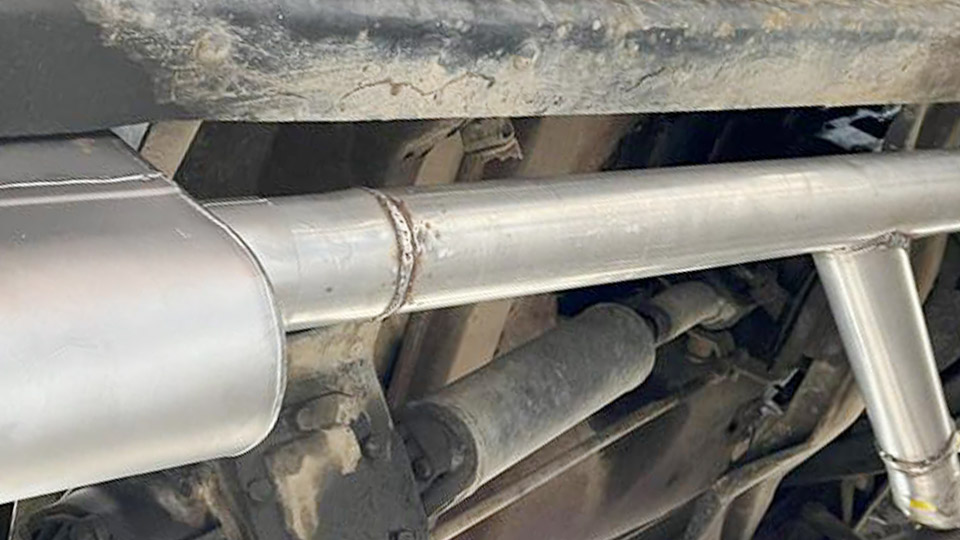
Image by steeldata
Why Weld Reinforcement Exists and Its Role in Joint Performance
Weld reinforcement forms naturally as filler metal fills the joint and solidifies. It compensates for minor variations in fit-up, penetration, and shrinkage while providing a buffer that helps the weld achieve full cross-sectional strength equivalent to or greater than the base metal.
In groove welds, the additional metal above the plate surface distributes load across the joint, but only when the height stays within controlled limits.
Excessive reinforcement does the opposite: it increases the effective thickness locally while creating sharp transitions at the weld toes. This geometry raises the stress concentration factor, reducing fatigue resistance under cyclic loading far more than many realize.
Conversely, insufficient reinforcement (flush or concave profiles in certain applications) can lead to underfill, reduced throat thickness, and premature failure in tension or bending.
Code Limits and Acceptance Criteria for Weld Reinforcement
Different codes establish maximum allowable reinforcement based on material thickness, service conditions, and joint type. These are not arbitrary; they balance strength, inspectability, and performance.
AWS D1.1 Structural Welding Code – Steel typically limits face reinforcement on groove welds to 1/8 inch (3 mm) maximum for most applications, regardless of thickness in many cases. This keeps the toe angle favorable and prevents excessive stiffness.
ASME Section III and related piping codes provide tiered limits. For base material up to 1 inch thick, maximum reinforcement is often 3/32 inch; it increases gradually for thicker sections up to 5/16 inch for material over 5 inches. Piping applications under ASME B31.3 reference similar tables, with emphasis on root reinforcement as well.
API standards for pipelines are stricter in some contexts, often targeting 1/16 inch nominal with tolerances up to 1/8 inch total, prioritizing smooth profiles for flow and fatigue in pressurized systems.
Always verify the specific WPS and applicable code. For critical fatigue-loaded structures, engineers may specify flush grinding or even tighter limits (e.g., 1/16 inch or less).
Measuring Weld Reinforcement Accurately
Use dedicated weld gauges such as the AWS Gauge or Hi-Lo gauge for reliable field measurements. Place the gauge legs on the base metal surfaces adjacent to the weld and lower the pointer or slide to the highest point of the crown.
Read the reinforcement height directly. For precision on curved surfaces like pipe, ensure the gauge bridges the weld without rocking.
Cross-section macro-etch samples or ultrasonic methods provide lab-level verification but are impractical for every production weld. Visual inspection combined with gauge checks satisfies most code requirements when performed by qualified personnel.
Factors Influencing Weld Reinforcement Height
Welding Process Effects
SMAW (Stick): Produces moderate reinforcement due to intermittent deposition and slag coverage. Electrode angle, amperage, and travel speed heavily influence bead profile. Higher currents and slower travel increase buildup.
GMAW/MIG: Often yields higher reinforcement with spray or globular transfer modes because of continuous wire feed and high deposition rates. Short-circuit mode on thinner material allows better control but can result in inconsistent height if parameters fluctuate.
FCAW: Self-shielded or gas-shielded variants deposit rapidly, leading to convex beads unless travel speed is optimized. Flux core characteristics affect slag detachment and final crown shape.
GTAW/TIG: Offers the finest control. Precise filler addition and heat management produce low, uniform reinforcement ideal for high-quality or thin-section work. Autogenous TIG on thin material may require no added reinforcement.
Parameter Adjustments for Control
- Travel Speed: Faster speeds reduce reinforcement height by limiting dwell time and metal deposition per unit length.
- Voltage and Amperage: Higher voltage widens the arc and can flatten the bead; amperage directly affects melt-off rate.
- Wire Feed Speed (MIG/FCAW): Matches deposition to travel speed to avoid excess buildup.
- Electrode/Work Angle: A slight drag angle (5–15°) in SMAW helps control puddle and reinforcement profile.
- Heat Input: Calculated as (Amps × Volts × 60) / Travel Speed (ipm). Lower heat input generally minimizes excessive crown while maintaining fusion.
Joint design also matters. Wider groove angles or larger root openings demand more filler, naturally increasing potential reinforcement unless multi-pass techniques with stringer beads are used.
Process-Specific Techniques for Optimal Reinforcement
Groove Welds in Plate and Pipe
For butt joints, aim for slight convexity that blends smoothly into the base metal at a toe angle ideally greater than 135° (less abrupt transition). In pipe welding, root pass reinforcement (internal) must avoid excessive protrusion that restricts flow or creates turbulence. Hot passes and cap passes build controlled layers.
Multi-pass welding allows incremental control: each pass can be adjusted to correct the profile of the previous one. Weave techniques versus stringer beads affect width and height—narrow stringers often produce more consistent, lower reinforcement.
Fillet Welds vs. Groove Welds
Fillet welds have different considerations. Leg size and throat determine strength more than face reinforcement, but excessive convexity still creates stress risers at the toes. Codes like AWS D1.1 address convexity limits separately from groove reinforcement.
When and How to Remove Excessive Reinforcement
Grinding is the most common correction. Use a flap disc or grinding wheel to feather the crown down to code limits while maintaining a smooth transition. Avoid undercutting the base metal or creating a concave profile that reduces effective throat.
In fatigue-critical applications, flush grinding removes the stress concentration entirely, significantly improving life. This adds labor and requires careful restoration of any lost material if the weld was already marginal in size. Always blend toes gradually—abrupt grinding creates new notches.
Mechanical peening or other post-weld treatments can sometimes mitigate toe stresses without full removal, but these are supplementary, not replacements for proper initial control.
Material and Thickness Considerations
Thicker sections tolerate slightly higher absolute reinforcement per code tables because the relative impact on stiffness decreases. However, the stress concentration effect remains geometry-driven. High-strength steels (e.g., over 70 ksi yield) are more sensitive to toe angles and demand tighter control or post-weld grinding.
Dissimilar thickness joints require measuring reinforcement from the higher surface. Alignment (hi-lo) affects apparent reinforcement and must be addressed in fit-up.
Impact on Mechanical Properties
Adequate reinforcement enhances tensile strength by increasing the load-bearing section. Studies show it can boost joint efficiency, but beyond optimal height, fatigue performance drops due to the notch effect at the toes.
The transition radius and angle between weld and base metal dominate fatigue behavior more than height alone in many cases.
In pressure vessels or piping, excessive internal reinforcement can also affect corrosion resistance or flow characteristics.
Common Decision Points in the Shop or Field
Production vs. Code Compliance: High-deposition processes save time but may require more grinding. Calculate total cost including labor for rework.
Position: Overhead and vertical welding naturally produce less reinforcement due to gravity; flat position allows higher deposition but risks excess.
Inspection Level: Visual (VT) catches gross excess; NDT like UT or RT may reveal associated issues like lack of fusion under heavy caps.
Repair Strategy: For minor excess, grinding suffices. Severe cases may need weld removal and re-welding to avoid compromising the heat-affected zone.
Advanced Considerations for Professionals
In high-cycle fatigue environments, finite element analysis or notch stress approaches quantify the exact penalty of a given reinforcement profile. Weld toe dressing (grinding or TIG remelting) improves fatigue class ratings substantially.
For automated welding (robotic MIG or submerged arc), parameter optimization through trial runs and laser profiling ensures consistent reinforcement across long seams.
Real-World Application Insight
Successful welders and inspectors treat reinforcement not as an afterthought but as a controllable variable that balances deposition efficiency against long-term performance.
The best outcomes come from procedure qualification that includes realistic reinforcement targets, followed by disciplined parameter control and gauge verification on every critical joint. This approach minimizes rejects, reduces grinding time, and delivers welds that perform reliably under load.
In demanding applications, the true measure of weld quality is often the effective stress concentration at the toe rather than the crown height alone. Mastering bead geometry through experience and data-driven adjustments separates adequate welds from exceptional ones that exceed design life expectations.
FAQ
What is the typical maximum weld reinforcement allowed by AWS D1.1?
For most groove welds, it is 1/8 inch (3 mm). Always confirm with the specific clause and joint details.
Does more weld reinforcement make the joint stronger?
Slight positive reinforcement helps achieve full strength, but excessive height introduces stress risers that reduce fatigue life without adding meaningful tensile benefit.
How do you reduce excessive reinforcement in MIG welding?
Increase travel speed, reduce wire feed speed or voltage slightly, or switch to a narrower weave/stringer technique while maintaining proper fusion.
Can you leave excessive reinforcement if it passes visual inspection?
No—codes explicitly limit it. Excessive crown requires removal to meet acceptance criteria, even if other aspects appear sound.