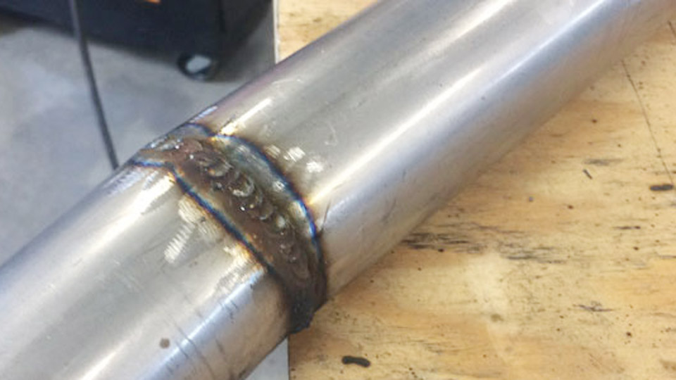
Welding thin sheet metal with MIG often leads to frustration: burn-through holes appear suddenly, panels warp out of alignment, or welds lack fusion despite careful setup. These issues stem from mismatched heat input, wire selection, or joint preparation on materials typically 24 to 18 gauge (0.5–1.2 mm thick).
MiG welding sheet metal demands low, controlled heat to achieve strong, clean joints without distortion—critical for auto body repair, fabrication projects, HVAC components, and custom brackets.
Mastering these parameters separates functional repairs from professional results. Proper settings and technique preserve material integrity while delivering reliable penetration and minimal post-weld cleanup.
Image by metakov
Challenges of MIG Welding Thin Materials
Heat Management and Distortion Risks
Thin sheet metal conducts heat rapidly but has low thermal mass, so even brief excessive input causes warping or burn-through. Short-circuit transfer mode excels here because it operates at lower voltages and amperages than globular or spray modes, allowing the wire to bridge the arc in short bursts that limit continuous heat.
Travel speed must stay high—often 10–20 inches per minute (ipm)—to avoid concentrating energy. On 20-gauge material, pausing even briefly can drop the puddle through the panel.
Pulsed MIG further refines control by alternating high-peak current for droplet transfer with low background current for cooling, reducing overall heat input significantly compared to constant-voltage short-circuit.
Material Thickness Variations
Gauge thickness dictates everything. 24-gauge (~0.6 mm) requires the lowest settings; 18-gauge (~1.2 mm) tolerates slightly higher parameters but still demands caution. Overlap joints handle minor gaps better than butt joints, which need near-perfect fit-up to prevent holes. Always test on scrap of identical thickness and condition.
Equipment and Consumables Selection
Wire Diameter Choices
Select wire based on thickness and machine capability. For most sheet metal under 18 gauge, 0.023″ or 0.024″ solid wire is ideal—it melts at lower amperage, reducing heat input to the base metal.
0.030″ wire works on 18–16 gauge if your machine feeds it smoothly at low speeds, but it narrows the parameter window. Avoid 0.035″ for thin work; it requires more current to melt, increasing burn risk. ER70S-6 provides good wetting and deoxidizing for mildly dirty surfaces; ER70S-7 offers better flow and flatter beads for less grinding.
Shielding Gas Considerations
75% argon / 25% CO2 (C25) is the go-to mix for sheet metal. It produces a stable arc with less spatter and lower heat than pure CO2. Flow rates of 15–20 cubic feet per hour (CFH) suffice indoors; increase slightly outdoors but watch for turbulence. Pure argon suits stainless sheet but can cause lack of fusion on mild steel if not adjusted properly.
Power Source and Gun Setup
Machines with good low-end control (synergic or pulse-capable) simplify dialing in settings. Maintain short stickout—3/8″ to 5/8″ maximum—for stable voltage delivery and effective gas coverage. Longer stickout drops effective amperage and invites porosity.
Use a spool gun or quality drive rolls to prevent bird-nesting with thin wire. Clean contact tips frequently, as spatter buildup disrupts current.
Optimal MIG Welding Parameters for Sheet Metal
Voltage, Wire Speed, and Amperage Guidelines
Settings vary by machine, but general ranges provide starting points. Test and fine-tune on scrap.
For 24–22 gauge with 0.023″ wire: 13–15 volts, wire feed speed 130–160 ipm, resulting in roughly 30–50 amps. Travel speed 15–20 ipm.
For 20–18 gauge with 0.023–0.030″ wire: 15–18 volts, wire feed 100–200 ipm depending on exact diameter, aiming for 50–90 amps.
These produce short-circuit transfer with a soft crackle sound. Too high voltage creates a harsh arc and undercut; too low yields cold, ropey beads with poor fusion.
Example Parameter Table for Mild Steel Sheet (Approximate, Test on Scrap):
- 24 ga (0.6 mm), 0.023″ wire: 14V, 140 ipm WFS, ~40A, 18 ipm travel
- 20 ga (0.9 mm), 0.023″ wire: 15.5V, 160 ipm, ~55A, 16 ipm travel
- 18 ga (1.2 mm), 0.030″ wire: 16.5–17.5V, 120–150 ipm, ~70A, 14 ipm travel
Pulsed modes allow higher peak settings while averaging lower heat, useful for filling gaps or out-of-position work.
Adjusting for Joint Type and Position
Butt joints on flat sheet need the lowest heat to avoid melt-through. Lap joints tolerate slightly higher settings because the overlapping layer absorbs extra energy. Vertical or overhead demands even tighter control—reduce voltage by 0.5–1V and increase travel speed or use pulse to control the puddle.
Joint Preparation and Fit-Up
Surface Cleaning Protocols
Remove mill scale, rust, paint, oil, and coatings thoroughly. Use a dedicated grinder or flap disc for mild steel; solvents for oils. Contaminants cause porosity and weak fusion regardless of settings.
Clamp pieces securely with minimal gaps—ideally zero for butt joints. Even 1/16″ gaps invite burn-through on thin stock. Backing bars (copper or aluminum) behind the joint dissipate heat effectively for critical seams.
Edge Preparation and Joint Designs
Square edges suffice for thin material, but slight bevels or flanges improve access and strength in some applications. For auto body patches, flange the repair panel edges for lap strength. Tack welds should be small and spaced to allow heat escape; place them strategically and let cool between passes if needed.
Welding Techniques for Control and Quality
Stitch and Skip Welding Patterns
Avoid continuous beads on long seams. Use short 1/2″–1″ stitches, skipping ahead and returning after cooling. This distributes heat and minimizes distortion. On panels, alternate sides or sections to balance shrinkage forces.
Gun Angle and Travel Methods
Maintain a 10–15° push angle (forehand) for better shielding and flatter beads. Pull (backhand) can work but increases heat concentration. Keep consistent travel speed; hesitation creates buildup or holes. For stitch welds, trigger quickly—many pros use a “tack and move” rhythm with higher momentary settings for flatter results and less HAZ (heat-affected zone).
Managing Warpage in Practice
Anticipate shrinkage and use clamps, temporary braces, or peening after cooling. Weld from the center outward on large panels. For extreme cases, intermittent welding with full cool-down periods between segments preserves flatness.
Common Defects and Targeted Fixes
Burn-Through and Warping
Primary causes: excessive voltage/wire speed or slow travel. Reduce parameters, shorten stickout, increase travel speed, or switch to pulse. Copper backing helps extract heat.
Porosity and Lack of Fusion
Porosity signals contamination or poor gas coverage—clean metal, check for drafts, ensure proper flow and short stickout. Lack of fusion often results from cold settings or wrong angle; increase voltage slightly or improve fit-up.
Spatter and Undercut
Spatter increases with high voltage or dirty surfaces. Fine-tune for a soft arc. Undercut comes from excessive heat or poor angle—lower settings and direct arc more evenly into the joint.
Address issues immediately on test pieces rather than mid-project.
Advanced Considerations: Pulse MIG and Specialty Applications
Pulsed MIG expands capabilities on sheet metal by delivering controlled droplet transfer with reduced average heat. It minimizes distortion on large panels, reduces spatter cleanup, and improves out-of-position performance—valuable for automotive or curved fabrications.
For stainless or aluminum sheet, adjust gas (tri-mix for stainless) and wire (ER308L, ER4043) while maintaining low heat principles. Multi-pass techniques are rare on thin material; focus on single-pass quality.
Decision-Making for Your Projects
Successful MIG welding of sheet metal boils down to deliberate choices in wire size, gas, parameters, and heat control tailored to the exact gauge and joint. Prioritize 0.023″ wire and C25 gas for most mild steel work under 18 gauge, test settings rigorously, and employ stitch techniques with short stickout. These decisions yield strong, low-distortion welds that require minimal finishing.
An advanced insight: the best welders treat heat as the primary variable—mastering its input through pulse or precise short-circuit modulation turns challenging thin material into an opportunity for precise, high-quality fabrication that outperforms expectations in strength and appearance.
FAQ
What wire size is best for MIG welding 20-gauge sheet metal?
0.023″ solid wire is preferred for 20-gauge and thinner. It allows lower overall heat input while maintaining good arc stability and penetration. 0.030″ can work but requires more precise control to avoid burn-through.
Can you MIG weld sheet metal without burn-through?
Yes, by using short-circuit or pulsed transfer, thin wire (0.023″), low voltage (14–17V range), short stickout, fast travel speeds, and stitch welding patterns. Proper fit-up and backing further reduce risk.
What gas mixture works best for MIG sheet metal on mild steel?
75% argon / 25% CO2 provides excellent arc stability, low spatter, and good penetration with minimal heat compared to pure CO2. Maintain 15–20 CFH flow.
Is pulse MIG worth it for sheet metal work?
Pulse MIG offers significant advantages in heat control, reduced distortion, and cleaner welds, especially on larger panels or when filling small gaps. It’s particularly beneficial if your machine supports it, though skilled short-circuit technique suffices for many jobs.