Setting up a MIG welder correctly is critical for producing strong, consistent welds and avoiding common defects such as lack of penetration, excessive spatter, burn-through, and poor arc stability.
Whether you’re working with mild steel in a fabrication shop or tackling a DIY welding project, understanding how to setup and use a MIG welder directly affects weld quality, material efficiency, and overall productivity.
A properly configured machine requires more than simply selecting voltage and pulling the trigger. Wire size, shielding gas, polarity, wire feed speed, and material thickness must work together to create a stable arc and reliable fusion. Incorrect settings can lead to weak welds, costly rework, and failed inspections.
By learning the correct setup process and operating techniques, you can achieve cleaner welds, better penetration, and greater control across a wide range of welding applications.
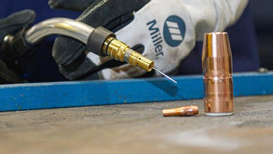
Image by thefabricator
MIG Welder Components and Their Functions
Power Source and Wire Feeder Integration
MIG machines combine a constant voltage (CV) power source with a wire feeder that pushes electrode wire through the gun at controlled speeds. Most home and shop units operate on 120V or 240V, with output ranging from 30-250+ amps.
The wire feeder drives amperage directly through feed speed, while voltage controls arc length and bead shape. Synergic or Auto-Set machines simplify this by linking parameters, but manual models require independent adjustment of voltage and wire speed (WFS).
MIG Gun and Consumables
The gun assembly includes the contact tip, nozzle, and liner. The contact tip transfers current to the wire and must match wire diameter precisely—typically 0.023″, 0.030″, 0.035″, or 0.045″.
Nozzles direct shielding gas; larger diameters improve coverage in drafty areas. Drive rollers grip the wire; use knurled rollers for flux-cored and smooth or U-groove for solid wire to avoid deformation.
Ground Clamp and Cable
A secure ground completes the circuit. Position the clamp close to the weld zone on clean metal for stable arc performance. Poor grounding causes erratic arcs, voltage drops, and spatter.
Workspace Preparation and Material Handling
Cleaning and Joint Preparation
Remove rust, paint, oil, mill scale, and moisture from the weld area using a grinder, wire brush, or flap disc. Contaminants cause porosity and weak fusion. For thicker materials, bevel edges for better penetration in multi-pass welds. Clamp pieces securely to minimize gaps, which exacerbate burn-through on thin stock.
Environmental Controls
MIG requires protection from wind and drafts that disrupt gas shielding. Work indoors or use screens. Maintain good ventilation for fumes. Position the workpiece for comfortable gun access, ideally flat or horizontal to start.
Choosing Wire, Gas, and Initial Parameters
Wire Selection by Application
Select wire diameter based on material thickness and amperage range:
- 0.023″ or 0.030″: Thin materials (up to 1/8″), lower heat input.
- 0.035″: General purpose, 1/8″ to 1/4″ steel.
- 0.045″: Thicker sections requiring higher deposition.
ER70S-6 works well for mild steel with some rust tolerance due to higher deoxidizers. ER308L suits stainless; ER4043 or ER5356 for aluminum.
Shielding Gas Options
- Mild Steel: 75% Argon / 25% CO2 (C25) offers stable arc, low spatter, and good penetration. 100% CO2 provides deeper penetration and lower cost but increases spatter.
- Stainless Steel: Tri-mix (90% He / 7.5% Ar / 2.5% CO2) or 98% Ar / 2% CO2 for corrosion resistance and bead appearance.
- Aluminum: 100% Argon for good cleaning action and arc stability.
Set gas flow to 15-25 CFH depending on nozzle size and conditions. Too low causes porosity; too high creates turbulence.
Starting Parameter Guidelines
Use material thickness to estimate amperage (roughly 1 amp per 0.001″ thickness). Then apply wire-specific multipliers for WFS in inches per minute (IPM).
Example Starting Settings for Mild Steel with C25 Gas (Approximate):
| Thickness | Wire Diameter | Voltage (V) | Wire Speed (IPM) | Gas Flow (CFH) |
|---|---|---|---|---|
| 20-18 ga (~0.03-0.05″) | 0.023″ | 15-17 | 90-150 | 15-20 |
| 1/8″ (0.125″) | 0.030-0.035″ | 17-19 | 150-250 | 18-22 |
| 3/16-1/4″ | 0.035″ | 19-22 | 220-350 | 20-25 |
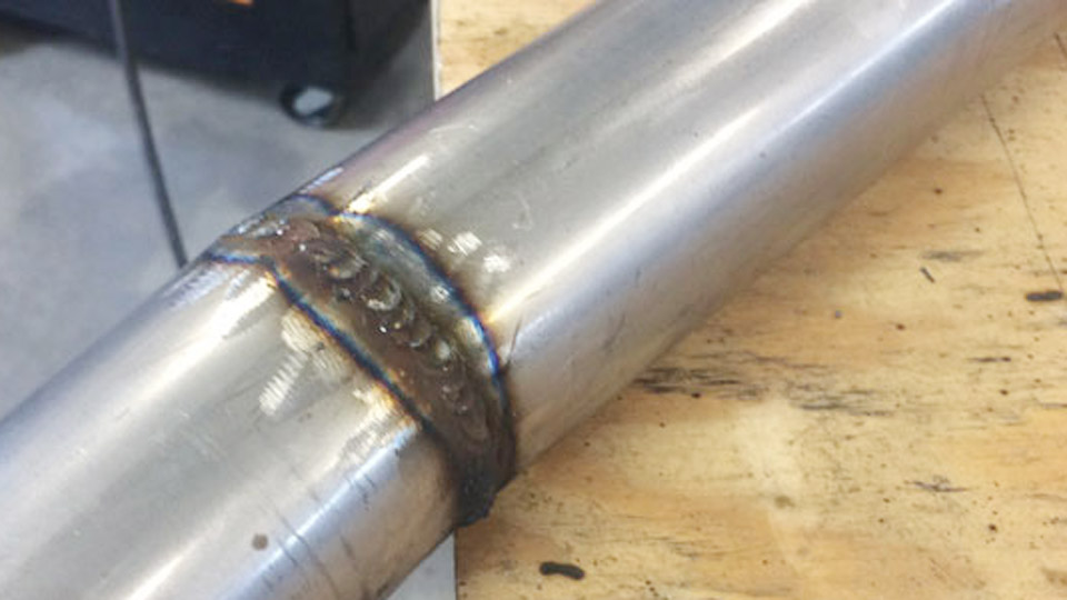
These serve as baselines. Fine-tune by sound (steady sizzle or bacon fry) and bead appearance.
Step-by-Step MIG Welder Setup Process
- Install the wire spool, ensuring proper direction and tension.
- Thread wire through drive rollers, liner, and gun. Trim and seat the contact tip.
- Connect shielding gas, set regulator, and purge lines.
- Attach ground clamp and power on the machine.
- Set polarity (usually DCEP for solid wire).
- Dial initial voltage and WFS per charts.
- Perform test beads on scrap of identical material and thickness. Adjust for crisp arc without stubbing or burn-back.
Check drive roller tension and gun liner condition regularly to prevent feeding issues.
MIG Welding Techniques for Consistent Results
Gun Positioning and Angles
Maintain 3/8″ to 1/2″ contact tip-to-work distance (stickout). Use a 10-15° travel angle (push for flatter beads and better gas coverage on solid wire; pull for deeper penetration with some flux-cored). Work angle varies by joint: 90° for butt joints, 45° for fillets.
Travel Speed and Motion
Match travel speed to deposition rate—too fast yields narrow, convex beads with poor tie-in; too slow causes wide beads, undercut, or burn-through. Use a slight weave or straight stringer depending on joint fill needs. Keep the wire at the leading edge of the puddle.
Multi-Pass Welding
For thicker materials, use multiple passes with interpass cleaning. Build layers with proper overlap to ensure fusion without excessive heat input that distorts the base metal.
Parameter Adjustments for Specific Materials and Thicknesses
Thin Materials (Under 1/8″)
Lower voltage and WFS to minimize heat. Use 0.023″ or 0.030″ wire and short-circuit transfer mode. Pulse settings on advanced machines help control heat further.
Medium to Thick Materials
Increase to spray transfer (higher voltage/WFS) for 1/4″+ sections. This produces a stable, high-deposition arc with minimal spatter. Preheat thick or dissimilar metals when necessary.
Stainless and Aluminum
Stainless requires precise heat control to avoid carbide precipitation; use lower heat and back-purge if possible. Aluminum demands higher WFS due to its conductivity, pure argon, and push technique for oxide cleaning. Clean aluminum thoroughly with a dedicated stainless brush.
Troubleshooting Weld Defects and Machine Issues
Porosity and Contamination
Causes include inadequate gas coverage, drafts, dirty metal, or leaks. Increase flow, check hoses/connections, and improve cleaning.
Spatter and Unstable Arc
Often from voltage too low/high, excessive stickout, or wrong gas. Shorten stickout to 3/8″, balance parameters, and ensure correct polarity.
Lack of Fusion or Penetration
Increase voltage or WFS, slow travel speed, or improve joint preparation. For cold starts, use a higher initial WFS.
Burn-Through and Distortion
Reduce heat input with lower settings, faster travel, or skip welding patterns. Use backing bars on thin sections.
Monitor for wire feeding problems like bird-nesting (adjust roller tension) or contact tip wear.
Advanced Setup Considerations for Performance
Incorporate inductance control on capable machines to soften the arc for thin materials or reduce spatter. For repetitive work, record successful parameters or use synergic programs. Consider post-flow gas settings (2-5 seconds) to protect the cooling puddle.
Regular maintenance—cleaning liners, replacing tips, and checking cables—extends equipment life and consistency.
Final Thoughts
Mastering MIG setup and use comes down to matching parameters to real material conditions and refining technique through deliberate practice on scrap. Consistent voltage-WFS balance, proper gas coverage, and controlled travel produce strong, visually clean welds that hold up under load.
The most advanced insight lies in understanding transfer modes—shifting from short-circuit on thin stock to spray on thicker sections optimizes deposition, heat input, and quality without chasing generic “perfect” settings. This decision-making separates reliable fabricators from those fighting their equipment.
FAQ
What voltage and wire speed should I start with for 1/8″ mild steel?
Begin around 17-19V and 150-250 IPM with 0.030-0.035″ wire and C25 gas. Run test beads and increase voltage for a smoother arc or adjust WFS for penetration.
How do I know if my shielding gas flow is correct?
15-25 CFH is typical. Listen for a steady arc and inspect for porosity. Too much flow causes turbulence; too little allows contamination.
Can I use MIG for aluminum and stainless on the same machine?
Yes, with the correct wire, gas (100% Ar for aluminum), and drive rollers. Dedicated guns or thorough cleaning between materials prevent contamination.
Why does my MIG weld keep stubbing or burning back to the tip?
Usually voltage too low or WFS too high. Increase voltage slightly until the arc stabilizes without excessive spatter.