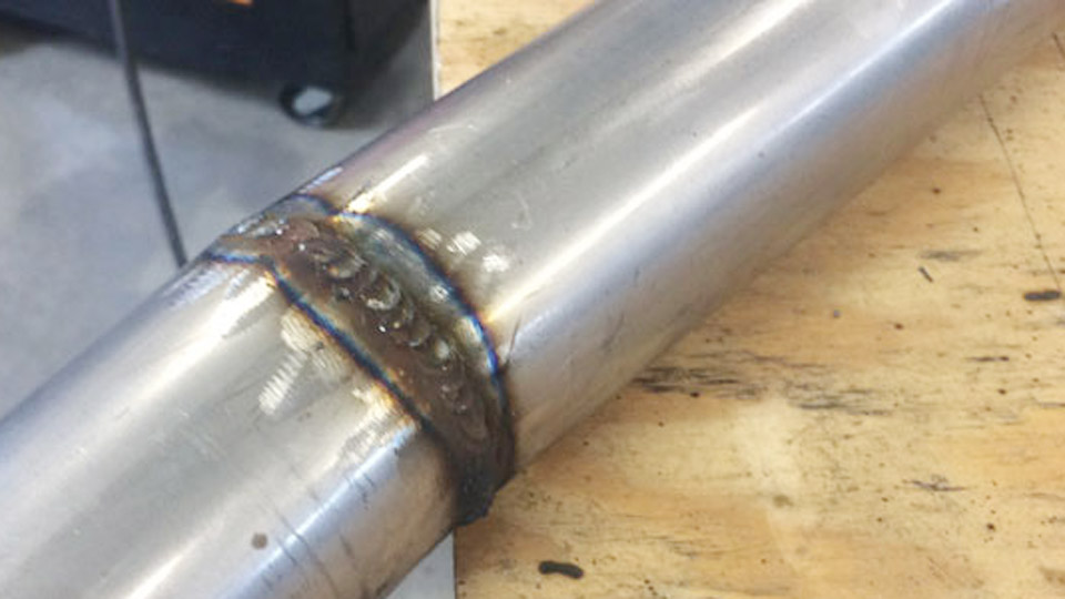
Vertical welding is one of the most challenging positions for MIG welders because gravity constantly works against proper puddle control. Learning how to weld vertical MIG correctly is essential for producing strong, consistent welds on structural steel, fabrication projects, and repair work where flat-position welding is not possible.
Poor technique in the vertical position can lead to excessive spatter, lack of fusion, undercut, cold lap, and uneven bead profiles that may fail inspection or require costly rework. Travel speed, gun angle, voltage settings, and puddle management all play a critical role in maintaining arc stability and achieving adequate penetration.
Whether you’re welding vertical-up for maximum strength or vertical-down for thinner materials, understanding the correct approach helps improve weld quality, reduce defects, and increase productivity. The key is matching technique and machine settings to the material thickness and welding application.
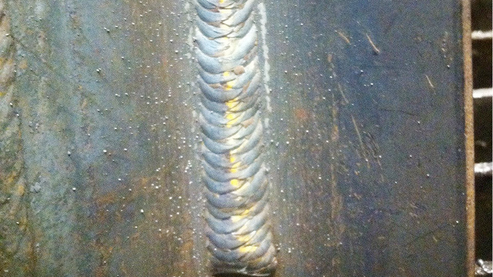
Image by bakersgas
Vertical MIG Welding Positions: Uphill vs. Downhill
Vertical welding involves two primary travel directions, each with distinct characteristics in heat input, penetration, and suitability.
Uphill Vertical MIG (3G Up)
Uphill welding moves from bottom to top. It allows higher heat input because the weld pool solidifies behind the arc while gravity helps contain it against the joint. This produces deeper penetration and stronger fusion, making it preferred for structural applications, thicker materials (over 1/8 inch or 3 mm), and load-bearing joints.
Uphill demands slower travel speeds and precise puddle control. The technique builds the bead progressively, stacking metal while maintaining fusion to the sides and root.
Downhill Vertical MIG (3G Down)
Downhill welding travels from top to bottom. It is faster, produces less heat input, and works well for thinner materials (under 1/8 inch) or cosmetic/root passes where speed matters more than maximum penetration. Gravity assists the pool flow, enabling quicker travel but risking shallower fusion and potential lack of penetration if settings are too cold.
Downhill suits sheet metal, non-critical fillets, or initial passes in multi-pass welds on thicker plate. It is less forgiving on dirty material or poor fit-up.
Key Decision Factors:
- Structural strength or code requirements → Uphill.
- Thin material or production speed → Downhill.
- Root pass on groove joints → Often downhill for speed, followed by uphill fill and cap passes.
Equipment Setup and Material Preparation for Vertical MIG
Successful vertical MIG starts before striking an arc. Poor preparation amplifies gravity-related issues.
Joint Preparation and Fit-Up
Clean the joint thoroughly: remove mill scale, rust, oil, paint, and moisture with a grinder, wire brush, or solvent. Contaminants cause porosity and poor fusion, worse in vertical due to limited puddle agitation.
For butt joints, use a 60–70° included angle bevel for thicker plate. Maintain a root gap of 1/16–3/32 inch (1.5–2.5 mm) for penetration without burn-through. Tack welds must be strong and spaced to prevent movement; grind tacks flush or incorporate them into the weld.
For fillet (T-joint) welds common in vertical, ensure tight fit-up. Gaps exaggerate sagging.
Position the workpiece for optimal access and visibility. Clamp securely; use fixtures or magnetic clamps to maintain alignment.
Wire, Gas, and Machine Selection
Wire: .030″ or .035″ ER70S-6 for most mild steel work (versatile on dirty material). Use .023″ for very thin sheet to reduce heat. Larger .045″ for heavy plate but harder to control vertically.
Shielding Gas: 75% Argon / 25% CO2 (C25) for best arc stability, low spatter, and bead appearance. 100% CO2 offers deeper penetration but more spatter and harsher arc—less ideal for vertical control.
Machine: Constant voltage (CV) MIG with good inductance control. Short-circuit transfer mode dominates vertical work for puddle control; globular or spray for thicker sections with adjusted parameters.
Check polarity (DCEP), ensure clean contact tip and liner, and use appropriate drive rolls for wire diameter.
MIG Parameter Settings for Vertical Welding
Flat-position charts serve only as starting points. Vertical requires reductions to control the puddle.
Adjusting for Uphill
Reduce voltage by 1–4 V and wire feed speed (WFS) by 20–30% compared to flat. This lowers heat input enough for control while maintaining fusion.
Example settings for mild steel (.035″ ER70S-6 wire, C25 gas, short-circuit transfer):
- 1/8″ (3 mm) plate, fillet: ~18–20 V, 180–250 ipm WFS (approx. 90–130 A).
- 1/4″ (6 mm) plate: ~19–21 V, 200–280 ipm.
- Thicker multi-pass: Similar per pass, with stringers or controlled weaves.
Short stick-out (3/8–1/2 inch or 10–13 mm) is critical for stable arc and penetration.
Adjusting for Downhill
Further reduce settings or increase travel speed. Use near-flat parameters but move faster to avoid excessive buildup or burn-through on thin material.
Monitor arc sound (crackling for short-circuit) and puddle behavior. Adjust voltage for arc length: too low causes stubbing; too high causes spatter and poor control.
Voltage-Wire Speed Relationship: Use machine charts or the rough guideline of 1 amp per 0.001″ material thickness, then fine-tune. Test on scrap in the same position.
Gun Technique and Manipulation in Vertical MIG
Torch angle and movement control puddle shape against gravity.
Torch Angles
- Travel Angle: 10–15° push (gun leading the puddle) for uphill to direct shielding gas and heat forward. Slight drag or neutral for downhill.
- Work Angle: For fillets, 45° to both plates, adjusted slightly to favor the vertical plate and prevent undercut. Keep near perpendicular (±10°) overall.
Maintain consistent short stick-out. Longer stick-out reduces penetration and destabilizes the arc vertically.
Uphill Welding Techniques
Use a triangle or Christmas tree pattern:
- Establish a small puddle at the root.
- Move the arc upward along one side, pause briefly at the toe to fuse and fill.
- Cross to the opposite side in a diagonal, pause again.
- Return through the center slightly higher, repeating to build layers.
This deposits metal on the sides while the center fills naturally. Pause times are short (fractions of a second) to avoid sagging. Watch the leading edge of the puddle for penetration.
Weave patterns work for wider beads but require tighter control to prevent undercut.
Downhill Welding Techniques
Use a straight or slight zigzag with faster travel. Keep the gun on the leading edge of the pool. The motion resembles a narrow “C” or “U” backward for some welders. Focus on speed to prevent the pool from running ahead or causing cold laps.
Multi-Pass Vertical MIG Strategies
Thick materials require multiple passes. Plan the sequence:
- Root pass: Often stringer or slight weave for fusion.
- Filler passes: Build thickness with overlapping beads, cleaning between passes.
- Cap pass: Slightly wider for contour.
Interpass temperature control matters—allow cooling if heat builds excessively, or use heat management techniques on large fabrications. Back-gouge if needed for full penetration grooves.
Material-Specific Considerations
Mild Steel
Most common. ER70S-6 with C25 gas performs reliably. Adjust for thickness as noted. Vertical is excellent for truck frames, structural repairs, and shop fixtures.
Stainless Steel
Use tri-mix gas (90% He / 7.5% Ar / 2.5% CO2 or similar) and matching wire (e.g., ER308). Lower settings due to higher thermal conductivity; watch for distortion.
Aluminum
Vertical aluminum MIG is challenging due to high fluidity. Use pure argon, push technique, and higher travel speeds. .030″ or .035″ ER4043/5356 wire. Specialized pulse MIG helps control the puddle significantly.
Always match filler to base metal and consult WPS for critical work.
Troubleshooting Vertical MIG Weld Defects
Sagging or Rolled Beads: Settings too hot or travel too slow. Reduce voltage/WFS or increase speed. Tighten weave/pauses.
Undercut on Toes: Travel too fast on sides or incorrect angle. Pause longer at edges; adjust work angle toward the plate.
Lack of Penetration/Fusion: Cold settings, long stick-out, or poor cleaning. Increase voltage slightly or shorten stick-out; ensure root access.
Excessive Spatter: Voltage too high, gas flow wrong (20–25 CFH typical), or dirty material. Check connections and polarity.
Porosity: Gas coverage issues (wind, leaks), moisture, or contaminants. Increase flow slightly or improve shielding with nozzle extensions if needed.
Test welds destructively on scrap—bend, break, or section them—to verify settings before production.
Advanced Insights for Professional Results
For code or high-performance vertical MIG, consider waveform-controlled machines with pulse or arc control features that stabilize short-circuit transfer. These reduce spatter and improve puddle control dramatically on vertical.
Track heat input (kJ/in) for qualified procedures: Heat Input = (Voltage × Amperage × 60) / Travel Speed (ipm). Uphill typically runs higher acceptable inputs than downhill.
Practice on scrap in the exact position and joint type. Muscle memory for puddle watching develops faster with consistent short stick-out and deliberate pauses than with random movement.
Performance Takeaway
Vertical MIG success hinges on deliberate heat reduction, short stick-out, and side-to-side puddle management rather than chasing speed.
Uphill delivers superior mechanical properties for demanding applications when executed with these controls, while downhill excels in efficiency on appropriate jobs.
The best welders select the direction based on material thickness, joint requirements, and service conditions—not habit.
FAQ
What is the best MIG setting for vertical uphill welding on mild steel?
Reduce flat-position voltage by 1–4 V and wire speed by 20–30%. For .035″ wire on 1/8″ steel, start around 18–20 V and 180–250 ipm WFS. Test and adjust for stable short-circuit transfer with good toe fusion.
Should I weld vertical MIG uphill or downhill?
Uphill for strength and penetration on thicker material or structural work. Downhill for speed on thin sheet or root passes. Choose based on load requirements and thickness, not convenience.
Why does my vertical MIG weld sag or have undercut?
Usually too much heat (high voltage/WFS), slow travel, or insufficient pauses at the toes. Shorten stick-out, reduce parameters, and use a triangle/weave with deliberate side dwells.
Can I use the same settings for vertical as flat MIG?
No. Vertical requires lower heat input to control the puddle. Always start lower and fine-tune on scrap in position. Door charts are for flat—adjust accordingly.