Frustrated with inconsistent MIG welds—porosity on thin sheet, lack of penetration on thicker plate, or excessive spatter ruining your project? The right MIG welding wire speed and voltage chart delivers the precise starting points you need for clean, strong results across materials and thicknesses.
These two controls primarily determine arc stability, heat input, penetration, and bead profile. Mastering their interaction separates hobbyist trial-and-error from reliable, repeatable performance for DIYers, students, and professionals.
This guide provides practical charts, material-specific adjustments, and decision-making insights based on real-world parameters. Use them as reliable starting points, then fine-tune on scrap for your exact setup.
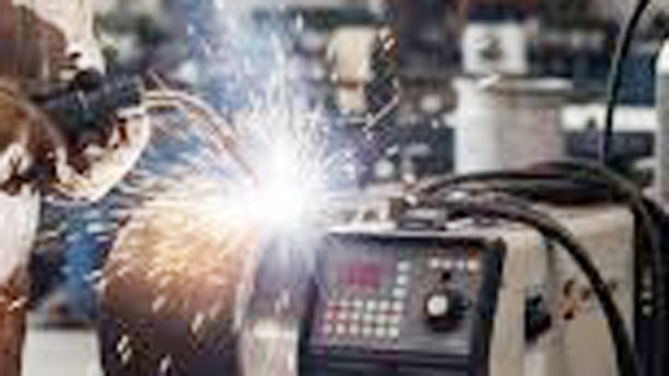
Image by yeswelder
Understanding Wire Feed Speed and Voltage in MIG Welding
How Wire Feed Speed Controls Amperage and Deposition
Wire feed speed (WFS), measured in inches per minute (IPM), directly influences welding amperage and the volume of filler metal deposited.
Higher speeds increase current because the wire contacts the workpiece more frequently, generating more heat for deeper penetration. Lower speeds reduce heat, suiting thin materials and minimizing burn-through.
Manufacturers provide multipliers for quick calculations when charts are unavailable. For 1/8-inch (125A target) mild steel:
- .023″ wire: 3.5 IPM per amp → ~438 IPM
- .030″ wire: 2 IPM per amp → 250 IPM
- .035″ wire: 1.6 IPM per amp → 200 IPM
- .045″ wire: 1 IPM per amp → 125 IPM
These serve as baselines. Actual output depends on machine, gas, and technique. On many machines, WFS primarily sets amperage while voltage remains relatively constant.
Voltage: Arc Length, Bead Shape, and Stability
Voltage controls arc length and influences bead width and height. Higher voltage lengthens the arc for wider, flatter beads with better wetting at the toes. Lower voltage shortens the arc for narrower, more convex beads.
Incorrect voltage causes issues: too high leads to erratic arcs and undercut; too low causes stubbing, poor starts, and excessive spatter.
Balance is critical. Set WFS first based on thickness and wire diameter, then adjust voltage for a stable, crisp arc that produces the desired “frying bacon” or consistent crackle sound in short-circuit transfer.
Key Interactions and Transfer Modes
Wire speed and voltage together determine metal transfer mode:
- Short-circuit: Low voltage (14-22V typical), moderate-to-low WFS. Ideal for thin materials and all positions. Frequent wire contact and release creates a characteristic popping sound.
- Globular: Transitional, often unstable with more spatter.
- Spray: Higher voltage (24V+), higher WFS. Smooth, high-deposition transfer for thicker materials in flat/horizontal positions.
Shielding gas affects the transition. 75% argon/25% CO2 supports short-circuit well; higher argon mixes ease spray transfer.
MIG Welding Wire Speed and Voltage Charts by Material Thickness
Mild Steel with .030″ Wire (Most Common for Hobby/Shop Work)
Use ER70S-6 wire and 75/25 Ar/CO2 gas for excellent results.
Approximate Settings (Flat Position, Single Pass):
- 1 mm (20 ga): 15-16V, 90-140 IPM
- 2 mm (14 ga): 16-17V, 140-200 IPM
- 3 mm (1/8″): 17-19V, 180-260 IPM
- 4-5 mm (3/16″): 19-21V, 220-320 IPM
- 6 mm (1/4″): 20-23V, 280-380 IPM
Adjust upward slightly for multi-pass or out-of-position. For .035″ wire, reduce WFS by ~20% and increase voltage 1-2V for similar heat.
.023″ Wire for Thin Materials
.023″ wire excels on thin stock due to lower amperage requirements and better control.
- 0.6-1 mm: 14-16V, 100-180 IPM
- 1.5-2 mm: 16-18V, 150-250 IPM
Higher travel speeds prevent burn-through. Keep stickout to 3/8-1/2 inch.
.035″ and .045″ Wire for Thicker Sections
.035″ wire handles most general fabrication up to 1/4-3/8 inch effectively.
Typical for 1/4″ mild steel: 20-24V, 300-400 IPM depending on joint and position.
.045″ wire supports higher deposition for heavy plate or high-productivity work. Expect 22-28V and WFS in the 150-300 IPM range for thick sections, with correspondingly higher amperage.
Material-Specific MIG Settings: Steel, Stainless, and Aluminum
Mild Steel Parameters and Adjustments
Mild steel tolerates a wide range but responds best to C25 gas. Rule of thumb: ~1 amp per 0.001″ thickness. For vertical-up, reduce WFS 10-20% and voltage slightly for better puddle control. Horizontal fillets may need minor voltage increases for toe wetting.
Stainless Steel Considerations
Stainless requires 10-15% less amperage than mild steel due to lower thermal conductivity. Use tri-mix gas (90% He / 7.5% Ar / 2.5% CO2) or 98% Ar/2% CO2 for cleaner welds and less oxidation.
Example for 1/8″ stainless with .035″ wire: Start around 18-21V, 160-240 IPM. Lower heat input prevents distortion and sensitization. Back-purge when possible on pipe or thin sheet.
Aluminum MIG Welding Settings
Aluminum demands higher heat input (~25% more amperage) and faster travel speeds. Use 100% argon and preferably a spool gun for .030-.035″ wire (ER4043 or ER5356).
- 1/8″ aluminum: 21-24V, 400-600 IPM
- Thinner sheet (1-3 mm): Lower end of range with push technique and careful cleaning
Aluminum’s high thermal conductivity requires hotter settings and quicker movement to avoid lack of fusion or excessive melt-through. Preheating thick sections helps.
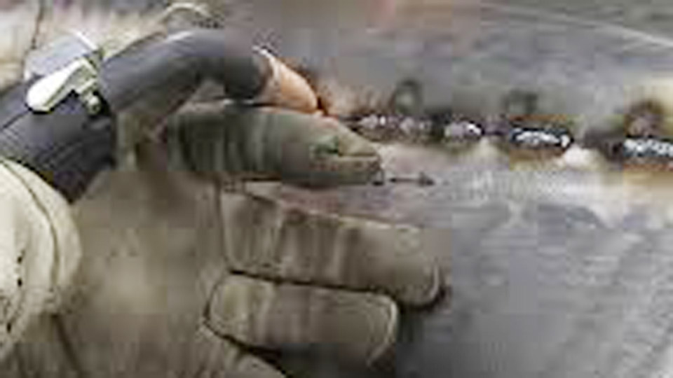
Fine-Tuning Techniques and Bead Diagnosis
Reading the Weld Bead for Adjustments
Inspect every test bead:
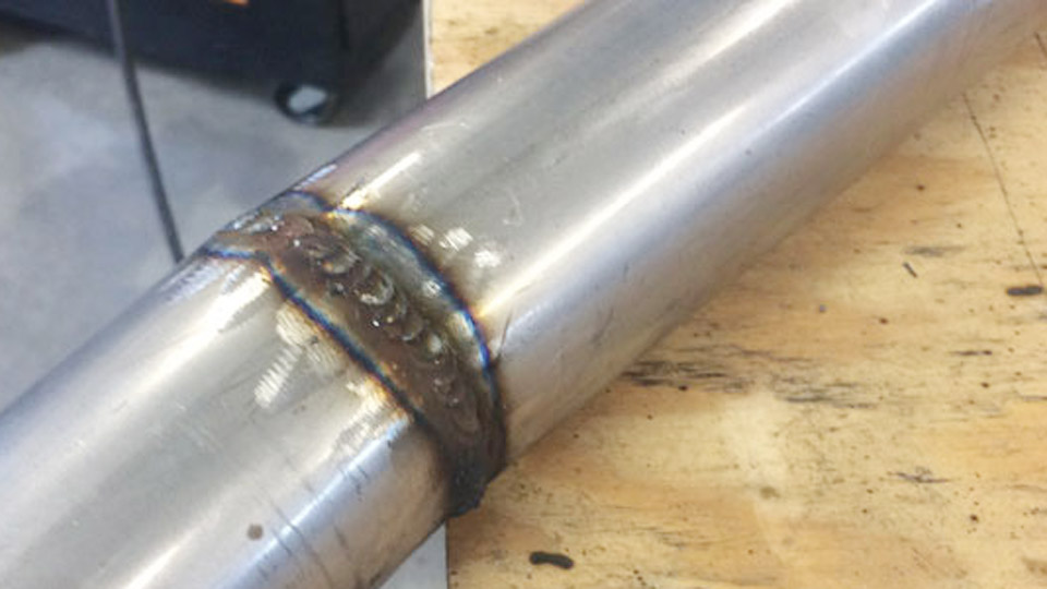
- Good bead: Flat to slightly convex profile, good toe wetting, consistent ripples, full penetration without undercut.
- Voltage too high: Wide, flat or concave bead, undercut, turbulent puddle.
- Voltage too low: Narrow, ropey/convex bead, poor tie-in, stubbing.
- WFS too high: Excessive heat, burn-through, heavy spatter, wide bead.
- WFS too low: Lack of penetration, narrow bead, poor fusion.
Listen to the arc: Stable short-circuit produces a steady sizzle or crackle. Erratic popping indicates imbalance.
Position, Joint Type, and Travel Speed Effects
Vertical and overhead demand lower parameters for puddle control. Increase travel speed to manage heat. Butt joints versus fillets may need voltage tweaks for proper reinforcement. Multi-pass welds on thick material often use slightly lower settings per pass to control distortion.
Maintain consistent 3/8-5/8″ stickout. Longer stickout reduces penetration; shorter increases it but risks burnback.
Advanced Decision-Making: Choosing Parameters for Real Projects
Machine Limitations and Synergistic Settings
Many modern inverters offer synergic or Auto-Set modes that link voltage and WFS based on material and thickness inputs. Use these as excellent starting points, then override for fine control. Older transformer machines require more manual balancing.
Duty cycle matters for production or long seams—higher settings reduce available on-time.
Wire Diameter Selection Strategy
Choose wire based on your most common work and machine capability:
- .023″: Thin auto body, light fabrication
- .030″: Versatile all-rounder
- .035″: General shop, thicker materials
- .045″: High deposition, heavy structural
Stock multiple sizes if your welder allows quick changes. Larger wires need more power but deposit faster.
Gas Flow and Environmental Factors
15-25 CFH typical. Increase in drafty areas; decrease if causing turbulence. Pure CO2 gives deeper penetration but more spatter than mixes. Test different mixtures for your application.
Troubleshooting Common Wire Speed and Voltage Issues
Porosity often traces to gas coverage or contaminated material rather than voltage/WFS alone. Excessive spatter points to voltage/WFS mismatch or wrong inductance (if adjustable). Lack of fusion on aluminum frequently results from insufficient voltage or dirty base metal.
When parameters seem correct but results vary, check contact tip condition, liner cleanliness, drive roll tension, and ground clamp connection. Small details compound in MIG.
FAQs
What is the best starting voltage and wire speed for 1/8 inch mild steel?
For .030″ wire with 75/25 gas, start at 17-19V and 180-260 IPM. Test on scrap and adjust voltage for optimal arc sound and bead profile. Thicker root passes or vertical positions may need slight reductions.
How do I convert wire feed speed to amperage?
Use manufacturer multipliers or test with a clamp meter. Roughly, .035″ wire at 200-300 IPM often produces 150-250A depending on the machine. Actual values vary; always verify with your setup.
Does wire speed or voltage have a bigger effect on penetration?
Wire feed speed has the greater direct impact on amperage and thus penetration. Voltage primarily affects arc length and bead shape. Balance both for optimal results.
Why do my settings work on mild steel but fail on aluminum?
Aluminum requires significantly higher wire speeds and voltage due to its thermal properties, plus 100% argon and faster travel. Clean oxide layer thoroughly and use push technique.
Final Thoughts
Mastering the MIG welding wire speed and voltage chart transforms your output quality and efficiency. Treat every chart as a proven starting framework, not a rigid rule—your machine, technique, and specific joint always have the final say.
The most advanced welders develop an intuitive feel for the arc through consistent practice and close observation of puddle behavior, bead geometry, and sound. Apply these parameters confidently, refine relentlessly on test pieces, and your welds will consistently meet or exceed expectations across projects.