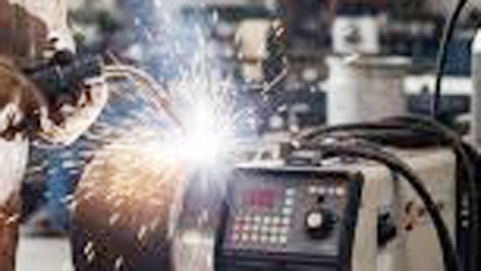
Exhaust pipe repairs and custom builds often fail at the joints due to burn-through on thin walls, weak penetration, or distortion that causes exhaust leaks and rattles. Learning how to MIG weld exhaust pipe correctly resolves these issues by balancing heat input, joint preparation, and technique for gas-tight, durable results on both mild steel and stainless tubing.
Proper MIG settings and methods prevent common failures like holes in 16-gauge material or cold laps that crack under vibration and heat cycling.
This matters for DIY fabricators and pros because a solid weld extends system life, maintains flow, and avoids repeated disassembly in tight undercarriage spaces.
Image by inthegaragemedia
Material Considerations for Exhaust Pipe Welding
Mild Steel vs. Stainless Steel Tubing
Mild steel exhaust pipe (typically aluminized or coated) offers lower cost and easier weldability but corrodes faster in road salt or moisture. Wall thickness usually ranges from 1.2–2 mm (16–18 gauge).
Stainless, often 409 or 304 grades, provides superior corrosion resistance for performance or longevity builds but demands tighter heat control to avoid sensitization and loss of chrome benefits.
Choose mild steel for budget street repairs where appearance and service life under 5–7 years suffice. Select stainless for custom headers, cat-back systems, or off-road use where exhaust gases and external exposure accelerate oxidation.
When joining dissimilar metals—such as mild steel muffler to stainless pipe—ER70S-6 wire still works in practice for non-critical applications, though 309 filler improves compatibility and reduces cracking risk at the interface.
Wall Thickness and Joint Types
Standard automotive exhaust runs 0.049–0.065″ thick. Thinner race tubing (under 0.050″) requires the lowest practical heat to avoid melt-through. Butt joints deliver smooth internal flow and minimal restriction for performance exhaust.
Lap joints (½” overlap) provide more forgiveness on fit-up and surface area for welding but can introduce slight flow disruption if not dressed internally.
Flange connections or slip-fit sections with clamps reduce welding volume but still need secure tacks. For repairs on used pipe, account for internal carbon buildup and external scale that affect arc stability.
MIG Welder Setup for Exhaust Pipe
Wire Selection and Drive Roll Tension
Use ER70S-6 solid wire for mild steel exhaust. .023″ or .025″ diameter excels on thin material because it allows lower overall heat input while maintaining stable arc and deposition. .030″ works on slightly thicker sections or when higher travel speeds are needed but increases burn-through risk on 16-gauge. Avoid .035″ unless welding heavier flanges or brackets.
Set drive roll tension just tight enough to feed without slipping or deforming the wire. Excessive tension flattens the wire and causes erratic feeding. For stainless-to-mild transitions, some shops run standard mild steel wire successfully; dedicated stainless wire (308/309) paired with tri-mix gas yields better corrosion performance where budgets allow.
Shielding Gas Choices
75% Argon / 25% CO2 (C25) provides the best balance of arc stability, penetration, and low spatter for mild steel exhaust. Pure CO2 runs hotter and cheaper but produces more spatter and less forgiving arcs on thin walls.
For stainless, tri-mix (90% He / 7.5% Ar / 2.5% CO2) or 98% Ar / 2% O2 reduces oxidation and improves bead wetting, though C25 remains practical for many mixed-metal repairs.
Flow rate: 20–25 CFH at the gun. Too low causes porosity; excessive flow creates turbulence and pulls in air. Use a gas lens or larger nozzle in drafty conditions for better coverage.
Voltage, Wire Speed, and Polarity
Set polarity to DCEP (electrode positive). Base amperage on the rule of roughly 1 amp per 0.001″ of thickness as a starting point, then fine-tune.
For 16-gauge (~0.060″) mild steel, target 40–70 amps with voltage around 15–18 V. Wire feed speed typically falls in the 200–300 IPM range depending on machine and wire diameter—lower for .023″ to control heat.
Test on scrap of identical thickness and condition. A stable arc sounds crisp without crackling (too cold) or humming excessively (too hot). Adjust voltage first for arc length, then wire speed for deposition. Many hobby machines with synergic settings simplify this, but manual fine-tuning beats presets on variable exhaust tubing.
Joint Preparation and Fit-Up
Clean the weld zone thoroughly. Remove rust, scale, paint, oil, and aluminized coating with a flap disc, wire wheel, or angle grinder to bright metal. Contaminants cause porosity and weak fusion. On used pipes, degrease inside and out where accessible.
Cut ends square with a tubing cutter or chop saw for butt joints. Deburr inside and outside edges. For best results, achieve near-zero gap—gaps force higher heat to bridge and increase distortion risk.
Use clamps, magnets, or Strong Hand tools to hold alignment. Tack every 90–180 degrees with short bursts, allowing cooling between tacks to minimize pull.
On thin tubing, a slight bevel or tight fit-up helps the puddle wet both sides without excessive filler. For slip joints, ensure ½” overlap and tack from opposite sides.
Welding Techniques for Thin Exhaust Tubing
Stitch and Tack Method vs. Continuous Beads
Continuous beads on thin exhaust often require cold settings that produce high, ropey welds with poor penetration.
Instead, use the hot and fast approach: higher voltage/amperage for short durations (½–1″ stitches or quick tacks), then pause to let the metal cool until the red glow fades. This delivers deep penetration without melting through the opposite wall.
Alternate sides or rotate the pipe to balance heat. On vehicle-installed pipes, work in small sections and use compressed air or a fan for faster cooling if needed. Push technique (forehand) usually improves visibility and gas coverage on round tubing.
Gun angle: 10–15 degrees push with ⅜” stick-out. Maintain consistent travel speed—too slow builds excess heat; too fast causes lack of fusion.
For butt welds on 1.5–3″ pipe, many welders lay the nozzle against the pipe and use muscle memory to guide the wire into the joint even when visibility is limited from one side.
Managing Heat Input and Distortion
Exhaust tubing distorts easily from uneven heating. Minimize total heat by:
- Short weld segments
- Cooling pauses
- Balanced tacking sequence (opposite sides)
- Lower wire speed where possible
Pulse MIG capability, if available, reduces average heat while maintaining penetration—ideal for very thin or stainless material. Without pulse, manual triggering achieves similar control. Expect some ovality on thin sections; plan to dress or use clamps during cooling.
On aluminized pipe, the coating burns off near the weld, leaving bare steel prone to rust—apply high-temp exhaust paint or ceramic coating after welding and cooling.
Common Challenges and Solutions
Burn-Through Prevention
Burn-through stems from excessive heat, long dwell time, poor fit-up, or oversized wire. Solutions include .023″ wire, reduced voltage, shorter stitches, and perfect cleaning. If a hole forms, build up edges with overlapping tacks before filling, or patch with a small doubler plate welded around the perimeter.
Porosity and Lack of Fusion
Porosity appears from dirty metal, insufficient gas flow, or wind. Fusion issues come from cold settings or fast travel. Address by re-cleaning, verifying gas coverage, and ensuring the arc melts both edges equally.
On rusty used pipe, flux-cored wire sometimes tolerates contamination better, though solid wire with gas yields cleaner results on new material.
Welding in Position and Tight Spaces
Vehicle exhaust often requires overhead or vertical welds. Short stitches and a 15-degree work angle help control the puddle. In cramped areas, a shorter gun or flexible neck improves access. Ground the clamp to clean metal close to the weld zone for stable arc.
Post-Weld Finishing and Inspection
Allow welds to cool naturally. Wire brush or grind excess reinforcement for smooth flow and appearance—especially important inside the pipe for performance systems. Pressure-test or smoke-test the system to verify no leaks. Apply exhaust-specific high-temperature paint (1200°F+ rating) or wrap for protection.
Inspect for cracks after the first heat cycle. Vibration and thermal expansion stress joints, so full penetration matters more than cosmetic bead height.
Equipment and Consumables Recommendations
- Welder: 140–200 amp MIG with good low-end control. Machines with infinite voltage adjustment outperform stepped models for thin work.
- Gun: 10–15 ft with Teflon liner for smooth .023″ feeding.
- Nozzles and Tips: Match wire size; keep spares clean.
- Accessories: Tubing cutter, flap discs, exhaust clamps, high-temp paint.
For shops or frequent builders, consider a spool gun if expanding to aluminum intercooler pipes later.
Real-World Decision Framework
Match settings and technique to the specific pipe: new mild steel allows slightly more aggressive parameters than old rusty stainless. Prioritize leak-free fusion over perfect cosmetics on hidden sections.
For visible custom work, spend time dressing beads and balancing heat for minimal distortion. When in doubt, practice on scrap cut from the same batch—exhaust tubing varies by manufacturer and age.
Advanced Insight: Pros often favor the hot-fast stitch on exhaust because it creates a low-profile, deeply penetrating nugget that resists fatigue better than cold, stacked beads.
The controlled heat-affected zone preserves more of the base metal’s original properties, extending service life under repeated thermal cycling far beyond what continuous low-heat seams achieve.
FAQs
What MIG wire size is best for exhaust pipe?
.023″ or .025″ ER70S-6 solid wire is preferred for most 16–18 gauge automotive exhaust. It runs cooler than .030″ or .035″, reducing burn-through while providing adequate penetration on thin walls.
Can you MIG weld stainless exhaust pipe to mild steel?
Yes. Standard ER70S-6 with C25 gas works for many applications. For better long-term corrosion resistance at the joint, use 309 filler wire and appropriate tri-mix gas, though results vary with heat input and service environment.
How do you avoid burning through thin exhaust tubing with MIG?
Use short ½–1″ stitches or tacks with cooling pauses, .023″ wire, 15–18 V range, and perfect joint fit-up with zero gap. Clean metal thoroughly and push the gun at a slight angle.
What gas and settings should I start with for exhaust pipe?
Begin with 75/25 Ar/CO2 at 20–25 CFH, 15–18 volts, and wire speed matched to 40–70 amps for 16-gauge material. Test and adjust on scrap—listen for a stable, crisp arc sound.
This approach to MIG welding exhaust pipe delivers reliable, leak-free joints when you prioritize controlled heat, clean preparation, and balanced technique over speed. Apply these parameters consistently and refine through deliberate practice on your specific materials for professional-grade results every time.