Many welders struggle with inconsistent nuggets, surface burns, or weak joints when setting up spot welds, especially across varying material thicknesses and types. The core issue often boils down to spot welding current and voltage—the primary drivers of heat input at the faying surface.
Incorrect settings lead to insufficient fusion or expulsion, compromising joint strength in automotive repairs, sheet metal fabrication, battery packs, or custom fabrication.
Getting these parameters right directly impacts nugget diameter, shear strength, and electrode life. Current (typically in thousands of amps) generates the resistive heat (Q = I²Rt), while voltage (usually low, 2–6 V) determines the machine’s ability to deliver that current effectively through the secondary circuit.
Understanding their interplay allows precise control, minimizing defects and maximizing productivity for DIY enthusiasts, students, and professionals alike.
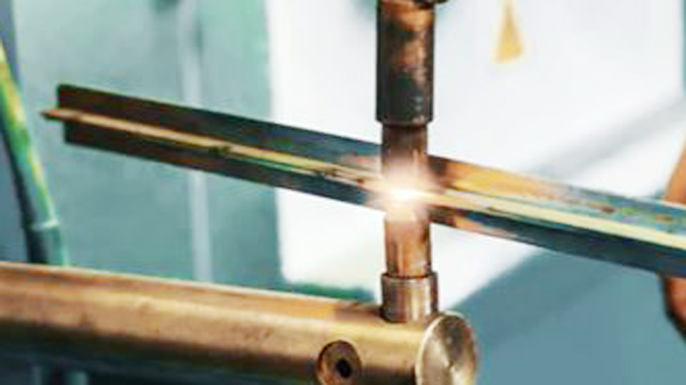
Image by yeswelder
Fundamentals of Heat Generation in Spot Welding
The Joule Heating Equation and Its Practical Application
Resistance spot welding relies on Joule’s law: heat input equals current squared times resistance times time. The interface between two sheets provides the highest resistance initially, concentrating heat to form the molten nugget. High current (4,000–30,000+ A) is essential because total resistance is low—typically micro-ohms—once contact is established.
Voltage on the secondary side stays low (2–6 V) due to the transformer stepping down from mains power. Machines deliver this through massive secondary currents.
For AC machines, voltage waveform and phase control affect effective heat; medium-frequency DC (MFDC) inverters provide more stable, controllable output with better efficiency for challenging materials.
Current Density and Nugget Formation Dynamics
Current density (A/mm²) at the electrode tip and faying surface dictates melting. Target nugget diameter follows the 4√t to 5√t rule (t = thinnest sheet thickness in mm) for adequate strength.
Too low a density yields small or no nugget; too high causes expulsion or indentation. Electrode face diameter (often 1–2 mm larger than target nugget) spreads current to control density.
Voltage indirectly influences this by enabling the machine to overcome impedance and sustain current against varying resistance as the nugget forms and softens.
Critical Factors Affecting Spot Welding Current and Voltage Requirements
Material Thickness, Conductivity, and Resistivity
Thickness is the dominant variable. Thicker sheets demand higher current and longer times to generate sufficient heat throughout the stack-up. For mild steel, current scales roughly with the square root of thickness or follows empirical charts.
Material properties matter equally:
- Mild/low-carbon steel: Moderate resistivity, good weldability.
- Stainless steel: Higher resistivity allows lower current but requires higher force.
- Aluminum: Extremely low resistivity and high thermal conductivity necessitate 2–3× the current of steel, shorter times, and clean surfaces.
Coatings like zinc on galvanized steel increase contact resistance initially but can cause expulsion if not managed with pre-heat pulses or adjusted parameters.
Electrode Force, Contact Resistance, and Surface Conditions
Force compresses the sheets, reducing contact resistance and preventing arcing. Insufficient force leads to high localized resistance and burns; excessive force flattens the nugget and reduces penetration. Typical forces range from 200–1,800+ lbs depending on thickness and material.
Surface oxides, scale, or contaminants raise resistance, requiring higher initial current or cleaning. Electrode tip condition (dressed to proper diameter and shape) maintains consistent current density—mushrooming increases face area and lowers density.
Machine Type and Duty Cycle Considerations
AC single-phase machines dominate hobby and light industrial use but suffer from power fluctuations. MFDC inverters offer precise current control, lower heat-affected zones, and better performance on aluminum or coated steels. Duty cycle limits continuous operation; high-current welds on thick material reduce it rapidly.
Recommended Spot Welding Parameters by Material and Thickness
Mild Steel Guidelines
For two equal sheets of mild steel on 60 Hz AC equipment, use these starting points (adjust via testing):
| Thickness (inches per sheet) | Gauge | Electrode Face Dia. | Force (lbs) | Current (A) | Weld Time (cycles) |
|---|---|---|---|---|---|
| 0.031 | 22 | 3/16″ | 400 | 8,000 | 5 |
| 0.040 | 20 | 1/4″ | 500 | 8,800 | 6 |
| 0.050 | 18 | 1/4″ | 650 | 9,600 | 8 |
| 0.062 | 16 | 1/4″ | 800 | 10,600 | 10 |
| 0.125 | 11 | 3/8″ | 1,800 | 15,600 | 20 |
Voltage is typically 2–4 V secondary. Increase current 10–20% for coated steel; use pulsation for thicker sections to control heat.
Stainless Steel Adjustments
Higher resistivity means lower current (often 20–30% less than mild steel) but higher force (20–30% more) to contain the nugget. Shorter times prevent excessive heat buildup.
Example for 0.050″ (18 ga): ~7,500 A, 6 cycles, 1,200 lbs force. Monitor for electrode sticking—dress frequently with Class 2 or 3 electrodes.
Aluminum and High-Conductivity Alloys
Aluminum requires significantly higher currents, lower forces, and very short times due to rapid heat dissipation. MFDC machines excel here.
| Thickness (inches per sheet) | Force (lbs) | Current (A) | Weld Time (cycles) |
|---|---|---|---|
| 0.032 | 400 | 18,000 | 2–3 |
| 0.050 | 500 | 22,000 | 4 |
| 0.063 | 550 | 24,000 | 5 |
Secondary voltage trends toward 4–6 V. Thorough surface cleaning (oxide removal) is non-negotiable. Use larger electrode faces and consider forging pulses.
Optimizing Parameters for DIY, Hobbyist, and Professional Setups
Benchtop and Portable Spot Welder Strategies
Home units (often 120V) handle lighter gauges (up to ~1/8″ combined mild steel). Start conservative: set force via spring or pneumatic adjustment, short weld times, and incrementally increase current (or % heat) while performing peel or chisel tests. Track nugget size—pull-out buttons indicate good fusion.
For capacitor discharge (CD) welders common in battery tab welding, energy (joules) and voltage settings replace direct current control. Higher stored voltage yields higher peak currents for thin materials.
Industrial and Automated Applications
Production lines use programmable MFDC controls with constant current mode, feedback loops, and multi-pulse schedules. Pre-heat pulses manage coatings; post-forge pressure solidifies the nugget without voids. Monitor dynamic resistance curves for real-time quality assurance.
Troubleshooting and Refining Current and Voltage Settings
Diagnosing Weak Welds or Insufficient Penetration
If nuggets are small or absent, increase current 5–10% or extend time slightly. Check electrode alignment and force—low force elevates resistance but may cause expulsion before full fusion. Clean surfaces and verify machine output with a current probe if available.
Addressing Burn-Through, Expulsion, and Indentation
Excessive current or time causes these. Reduce current, shorten time, or increase force. For expulsion on coated materials, add a pre-heat pulse at lower current to burn off zinc gradually. Dress electrodes to restore proper face diameter and prevent mushrooming that dilutes current density.
Electrode Life and Maintenance Impacts
High currents accelerate wear. Proper force and timely dressing extend life. Class 2 copper electrodes suit steel; specialized tips for aluminum reduce pickup.
Advanced Considerations: Pulsation, Slope Control, and Quality Verification
Pulsation (multiple short current pulses with cool times) widens the welding window for thick or coated materials by allowing heat dissipation and reducing distortion. Upslope/down-slope controls soften the current ramp to minimize initial expulsion.
Verify welds with destructive tests: peel test for nugget diameter, tensile shear, or cross-section macro-etching. Non-destructive options include ultrasonic testing in critical applications. Aim for consistent button pull-out exceeding minimum shear strengths per AWS or ISO standards.
Record successful schedules for repeatability—thickness, material, machine settings, and test results form the basis for future jobs.
Wrapping Up
Effective decision-making in spot welding comes down to matching current, time, and force to the specific material stack-up while verifying results through testing. Prioritize baseline charts tailored to your machine, then fine-tune iteratively.
For demanding applications, MFDC technology and pulsation schedules deliver superior consistency and strength. Mastering these parameters separates functional welds from optimized, production-ready joints—delivering reliable performance every time.
FAQ
What is the typical voltage range in spot welding?
Secondary voltage is low, generally 2–6 V, sufficient to drive high currents (thousands of amps) through low-resistance paths. Exact value depends on machine design and load; focus primarily on current output and time.
How do I calculate starting current for spot welding a specific thickness?
Use industry charts as baselines (e.g., ~8,000–10,000 A for 0.040–0.062″ mild steel). Rough rule-of-thumb: current (A) ≈ 100,000 × total thickness (inches), then adjust. Always test and refine.
Why does aluminum require different spot welding current and voltage than steel?
Aluminum’s high conductivity demands much higher current (often double or more) and shorter times to form a nugget before heat dissipates. Voltage may trend higher (4–6 V) to support the elevated current.
What happens if spot welding current is too high?
Excessive current causes expulsion (metal spray), surface burning, deep indentation, electrode sticking, and reduced nugget integrity. It also shortens electrode life dramatically.