When your Miller MIG welder suddenly stops feeding wire despite power to the machine, gas solenoid clicking, and a functioning fan, frustration builds quickly on the shop floor or in the garage.
The wire feed motor not engaging disrupts everything—from hobby projects to professional repairs—leading to inconsistent arcs, poor penetration, or complete downtime.
This issue with a Miller MIG welder wire feed motor not working often stems from electrical, mechanical, or consumable problems that require targeted diagnosis.
Understanding the root causes and systematic fixes restores reliable performance across models like the Millermatic series. Proper troubleshooting minimizes parts replacement costs and keeps your welding output high.
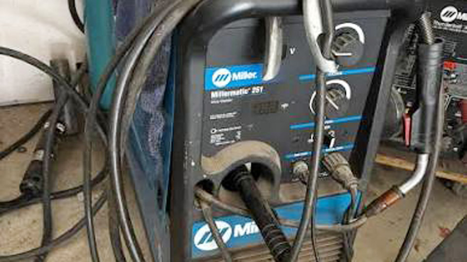
Image by welderamazing
Diagnosing the Core Problem: No Motor Rotation
Electrical Supply to the Motor
The wire feed motor in most Miller MIG welders operates on low-voltage DC, typically 12-24V, controlled by the circuit board and wire speed potentiometer. When you pull the trigger, check for voltage at the motor leads with a multimeter.
No voltage or fluctuating low readings (e.g., pulsing around 8V instead of steady higher output) point to board issues, bad connections, or trigger circuit faults.
Measure voltage directly at the motor terminals while the trigger is engaged (or use the machine’s wire inch/check button if available). Compare readings while adjusting the wire speed dial.
If voltage changes appropriately but the motor doesn’t spin, the motor itself or its gearbox is suspect. If no voltage reaches the motor, focus on the control board, fuses, or trigger wiring.
Trigger and Torch Circuit Issues
A common culprit is a faulty torch trigger or shorted trigger wires inside the cable. Miller guns have duty cycles; overheating can cause copper strands to break and short, leading to erratic or no motor response.
Test by bypassing the torch: short the trigger terminals on the machine’s Euro connector with a paperclip or jumper (safety first—unplug power and ground). If the motor runs, the problem is in the gun.
Inspect trigger wires for damage, especially near the handle or machine connection where flexing occurs. Spare wires in the conduit can sometimes be used for quick repairs.
Mechanical and Drive System Failures
Drive Rollers, Tension, and Alignment
Even if the motor has power, mechanical binding prevents effective feeding. Verify drive roll groove size and type match your wire (V-groove for solid steel, knurled for flux-cored, U-groove for aluminum). Misalignment or worn grooves cause slippage.
Tension arm settings matter critically: too loose leads to slippage and bird-nesting; too tight squashes the wire, wears bearings prematurely, and strains the motor. Set tension by feeding wire against a block until it slips, then add about half a turn. Over-tightening is a frequent mistake that accelerates wear on Miller’s drive systems.
Clean rollers regularly. Debris or flattened wire ruins grip. Replace if grooves are deformed.
Spool Hub and Wire Path
Excessive spool brake tension overloads the motor. It should prevent free-wheeling without dragging. Rusty or deformed wire from poor storage clogs liners and increases resistance. Always store spools in dry conditions.
Torch and Consumables Troubleshooting
Liner Condition and Installation
The liner transfers wire from the drive rolls to the contact tip. Kinks, debris buildup, or incorrect size/length cause jamming even with a healthy motor. Steel wire needs steel liners; aluminum requires Teflon or polymer. Cut liners slightly long and trim for a snug fit against the diffuser to prevent gaps that collect shavings.
Blow out liners with low-pressure air only as a temporary measure—replacement is better for worn ones. Replace periodically based on usage.
Contact Tip and Nozzle
A mismatched or worn contact tip (wrong ID or oblong hole) creates arcing inside the tip, leading to burnback and motor strain. For 0.030″ wire, ensure exact or slightly oversized tips, especially with gasless or aluminum wire that runs hotter.
Clean or replace tips frequently. Nozzle buildup restricts gas and indirectly affects feed consistency.
Advanced Electrical Diagnostics for Miller Machines
Circuit Board and Component Checks
Miller control boards handle motor speed via PWM or similar. Heat damage, blown components (look for charred triacs, capacitors, or small fuses), or dry solder joints are common after heavy use or trigger shorts. Visual inspection often reveals issues.
On models like the Millermatic 211 or 250, overheating protection or “Too Hot” messages may appear. Test the speed pot (potentiometer) for smooth resistance changes. Loose power jumpers, transformer secondary outputs (24V), or circuit breaker voltage drops also disrupt motor supply.
Motor Testing
Isolate the motor by disconnecting its leads and applying 12V DC from a battery or power supply (many 24V motors spin adequately on 12V for testing). Listen for humming (seized bearings/gears) versus smooth operation. Gearbox lubrication or cleaning may revive sticky units, but replacement is often practical for older machines.
Model-Specific Considerations for Miller MIG Welders
Millermatic Series (e.g., 140, 211, 252)
These popular units share common drive systems. Auto-set models may show different error behaviors. Check voltage selector switches or internal jumpers if recently moved. Capacitors on boards can hold charge—discharge safely before probing.
Heavier-duty models like the 250 handle more abuse but suffer board failures from prolonged trigger shorts without protection.
Preventive Maintenance Schedule
- Daily/Weekly: Clean drive rolls, check tensions, inspect wire.
- Monthly: Blow out torch, check liner, test trigger continuity.
- Annually or as needed: Replace liner, contact tips, drive rolls; inspect board for heat signs.
Consistent maintenance prevents most “motor not working” complaints.
Repair vs. Replacement Decisions
For DIYers and hobbyists, motor or board replacement is viable with parts availability from Miller or aftermarket. Professionals weigh repair costs against new machine value—newer inverters offer better reliability and features.
When sourcing parts, match exact specifications (voltage, RPM, mounting). Generic motors may fit but underperform.
Optimizing Wire Feed Performance Post-Fix
After resolving the motor issue, dial in parameters: match wire speed to voltage for stable arc. Test on scrap with proper stick-out (3/8″–1/2″ typical). Proper gas flow (20-25 CFH) and polarity prevent secondary issues that mimic feed problems.
For aluminum or flux-cored, slight tension and tip oversizing reduce headaches.
Real-World Application Insight
Effective troubleshooting of a Miller MIG welder wire feed motor not working comes down to isolating electrical supply from mechanical resistance and torch consumables. Prioritize quick bypass tests (trigger short, motor direct power) before deep disassembly.
This approach saves hours and parts. For high-duty applications, upgrading to a more robust feeder or gun pays dividends in uptime.
The most advanced insight: treat the entire wire path as a system—small misalignments compound under heat and load, turning minor wear into total failure. Master this, and your Miller setup delivers consistent, high-quality welds every time.
FAQ
Why does my Miller MIG welder motor hum but not spin?
This usually indicates a seized gearbox, bearings, or overloaded tension. Disconnect the motor and test directly; clean/lube the drive or replace if binding persists.
Can a bad trigger cause the wire feed motor not to work on Miller machines?
Yes. Shorted or worn trigger wires prevent the control signal from reaching the board/motor. Bypass testing confirms this quickly.
How do I test if the circuit board is bad in my Miller MIG welder?
Check for voltage at motor leads with trigger pulled and speed adjusted. No or incorrect voltage with good connections points to the board. Look for visible damage like burnt components.
What wire feed settings prevent motor strain on Miller MIG welders?
Use correct drive rolls/grooves, moderate tension (just past slippage), and proper liner/tip sizing. Avoid max tension or low-speed extremes for thin materials that may not provide enough load.