Knowing how to make a mold for aluminum casting is essential when producing accurate, repeatable metal parts for fabrication, repairs, or custom projects. A well-designed mold directly affects casting quality, dimensional accuracy, surface finish, and the amount of machining required afterward.
Poor mold design can lead to defects such as shrinkage cavities, gas porosity, misruns, and excessive flash, increasing material waste and rework before the part is ready for welding, machining, or assembly.
Whether you’re casting replacement components or creating parts for a fabrication project, understanding the correct mold materials, pattern design, gating, and venting principles helps improve consistency and reduce costly mistakes.
I’ll explain the fundamentals of making an aluminum casting mold, giving you the practical knowledge needed to produce stronger, cleaner castings that are better suited for downstream metalworking operations.
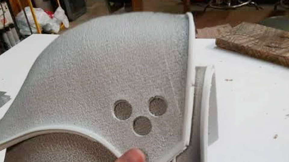
Image by r/Blacksmith
Why Mold Choice Determines Casting Success
Mold selection directly impacts surface finish, dimensional accuracy, production volume, and defect rates. Aluminum shrinks 1.0–1.3% as it solidifies, so patterns must compensate.
Poor venting or gating causes porosity, while mismatched thermal properties lead to cracks. Understanding trade-offs ensures you match the mold to your project—prototypes versus runs of 50+ parts.
Sand Molds: Versatile and Low-Cost for Most Shop Needs
Sand molds dominate hobbyist and small-shop aluminum casting due to low cost and flexibility for complex geometries. Green sand (silica sand + bentonite clay + water) or oil-bonded Petrobond provides good permeability and detail.
Mix Ratios and Preparation
Industrial mixes use 75-85% silica sand, 5-10% bentonite, and 2-5% water (target 3-3.3% moisture). For DIY, start with 9:1 sand-to-clay by volume. Test by squeezing: the mix holds shape with clean fracture edges. Too wet creates steam porosity; too dry collapses.
Flasks (cope and drag) contain the sand. Weld your own from 1/4-inch steel plate for durability or use wood for lighter duty. Size 12×12 inches for starter projects. Include alignment pins for repeatable closure.
Permanent Molds: For Higher Volume and Better Finish
Steel, cast iron, or graphite permanent molds suit repeated pours. H13 tool steel handles thermal cycling best for high-pressure or gravity die casting. These yield tighter tolerances (±0.010–0.015 inches) and smoother surfaces (125–250 Ra) than sand.
Graphite excels for small, detailed parts with excellent release and high-temperature stability up to 1650°C. Initial machining cost is higher, but reusability pays off beyond 50–100 cycles.
Investment and Lost Foam Molds: Precision for Complex Shapes
Investment (lost-wax) uses ceramic shells around wax patterns for thin walls and fine details. Lost foam employs polystyrene patterns vaporized by molten aluminum in dry sand—ideal for intricate, one-off engine or bracket designs.
Pattern Design and Preparation: The Foundation of Accurate Castings
Patterns must include draft angles (1–3° external, 2–5° internal) for clean release, plus shrinkage allowance. Use wood, PLA (3D-printed), or aluminum. Coat with shellac or parting compound. Fillets of 1.5–3 mm prevent hot spots and cracks.
Gating and Risering Decisions
Sprue (tapered pouring channel), runners, and risers feed metal and compensate shrinkage. Place gates at thicker sections to promote directional solidification. Vents (0.5–1 mm) every inch or so prevent gas entrapment. Simulation software helps, but shop testing with small pours refines placement.
Step-by-Step: Building a Basic Two-Part Sand Mold
This method suits most DIY welders. Assume a simple L-bracket pattern.
Prep the Drag: Place pattern face-down on a flat board inside the drag. Sift fine facing sand (1/4 inch layer) over it for detail. Fill with backing sand in 2–3 inch layers, ramming firmly (use a 2-lb hammer or maul head for even pressure). Strike off level.
Add Parting Line: Dust parting compound (talc or graphite). Position cope, insert sprue and riser pins. Ram cope sand similarly. Add vents by poking rods through.
Separate and Draw: Remove pins carefully. Lift cope straight up. Extract pattern gently—tap if needed. Repair any defects with small tools. Cut gates and runners with a spoon or blade for smooth flow.
Close and Secure: Realign halves with pins or clamps. Preheat mold slightly (around 200°F) if sand is damp to reduce moisture issues.
Pouring Prep: Melt aluminum to 1250–1350°F (depending on alloy, e.g., 356 or A356). Skim dross, degas if possible. Pour steadily into sprue. Allow cooling before shakeout.
Post-cast: Remove gates with angle grinder, inspect for defects, and weld as needed for hybrid assemblies.
Advanced Techniques: Improving Mold Performance
Core Making for Internal Features
Use resin-bonded or green sand cores for hollow sections. Core prints on patterns locate them accurately. Vent cores thoroughly—trapped gases cause blowholes.
Mold Coatings and Treatments
Apply refractory coatings to sand cavities for smoother finishes and heat resistance. For permanent molds, use die lubricants and preheat (150–400°C) to avoid thermal shock and soldering.
Lost Foam Specifics
Carve or CNC polystyrene foam. Coat with refractory slurry (joint compound works for DIY). Bury in dry sand, vibrate to compact. Pour—foam vaporizes ahead of metal. Control coating thickness and sand vibration for fill speed and surface quality.
Common Defects and Process Controls
Porosity stems from moisture, poor venting, or turbulent pour. Shrinkage voids from inadequate risers. Cold shuts from low pour temperature or thin sections. Track melt temperature, sand moisture (squeeze test), and ram density (aim 1.6–1.8 g/cm³). Test pours on scrap reveal issues early.
Alloy Considerations
356/A356 offers good castability and weldability. Add silicon for fluidity; magnesium for strength. Post-cast heat treatment (T6) enhances properties.
Equipment and Shop Setup for Safe, Efficient Casting
Beyond flasks and sand, invest in a crucible furnace, tongs, protective gear (face shield, gloves, apron), and ventilation. For welding integration, prepare castings for TIG or MIG by grinding flash and preheating thicker sections.
Real-World Applications in Welding and Fabrication
Mold-making enables custom fixtures, repair patches, or decorative elements that weld seamlessly to steel frames. In automotive or marine work, cast aluminum brackets reduce weight without sacrificing strength. Scale from one-offs to small batches as skills improve.
Decision-Making Summary
Choose sand for prototypes and large parts, permanent for volume, and lost foam/investment for complexity. Prioritize proper pattern draft, gating, venting, and temperature control—these technical decisions separate scrap from serviceable parts.
An advanced insight: mastering mold permeability and directional solidification lets you cast thin-walled, pressure-tight components that outperform off-the-shelf weldments in demanding environments.
FAQ
What is the best sand mix for aluminum casting molds?
A 9:1 silica sand to bentonite ratio with 3% moisture works reliably for most DIY pours. Adjust based on squeeze test for cohesion and permeability.
How much shrinkage should I account for in patterns?
Add 1.0–1.3% linear shrinkage allowance. Include 1–3° draft angles for easy release.
Can I reuse sand molds for multiple aluminum pours?
Green sand is typically single-use per mold but reclaimable by re-mixing. Permanent molds (steel/graphite) are designed for hundreds of cycles.
What temperature should aluminum be poured at for sand molds?
Aim for 1250–1350°F, adjusted for alloy and section thickness. Steady pour minimizes turbulence.