Fillet welds are among the most common joints in fabrication, yet many welders struggle with accurate time estimates. Overestimating leads to missed deadlines and inflated bids; underestimating causes rushed work, poor quality, and rework.
Learning how to calculate weld time for fillet welds directly impacts productivity, cost control, and weld integrity for DIY hobbyists, students, and professionals alike.
Precise weld time calculation combines weld volume, material deposition rates, travel speed, and operational factors. It enables better scheduling, material ordering, and process selection while avoiding defects from improper parameters.
I’ll discuss the practical formulas, real-world data, and decision-making insights tailored to common processes like SMAW, GMAW (MIG), FCAW, and GTAW (TIG).
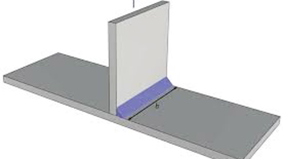
Image by structuralbasics
Understanding Fillet Weld Geometry for Time Calculations
Cross-Sectional Area and Volume Basics
The foundation of weld time calculation is the volume of weld metal required. For an equal-legged fillet weld, the theoretical cross-sectional area is a right triangle:
Area (A) = (leg size²) / 2
Where leg size (Z) is in consistent units (e.g., inches or mm). Multiply by weld length (L) for volume.
Example: A 1/4-inch (6.35 mm) leg fillet weld over 12 inches (305 mm) long has:
A = (0.25)² / 2 = 0.03125 in²
Volume = 0.03125 in² × 12 in = 0.375 in³
Account for reinforcement (typically 10-20% extra) and convexity. Real deposited volume often exceeds theoretical by 15-25% depending on technique and process.
Theoretical Throat vs. Actual Deposited Metal
The effective throat (0.707 × leg size for 45° fillets) determines strength, but time calculations use total deposited metal. Deep penetration processes (e.g., SAW or certain MIG settings) can reduce required leg size while maintaining throat, lowering volume and time.
Unequal leg fillets require adjusted area: multiply throat by face length and divide by 2. Always measure or specify legs accurately, as drawings often call for minimum sizes while actual deposition varies.
Accounting for Multi-Pass Fillets
Larger fillets (>1/4 inch or 6 mm) often need multiple passes. Calculate total volume across passes or use average deposition per pass. Multi-pass increases total time due to interpass cleaning, cooling, and repositioning, but allows better control in out-of-position welding.
Key Formulas for Weld Time Calculation
Arc Time from Deposition Rate
Arc time (minutes) = (Weld metal weight / Deposition rate) × 60
Weld metal weight (lbs or kg) = Volume × Density × (1 + reinforcement factor). Steel density ≈ 0.283 lb/in³ or 7.85 g/cm³.
Deposition rates (approximate lbs/hr deposited weld metal):
- SMAW (stick, 1/8″ E7018): 2.5–5.5 lb/hr
- GMAW/MIG (0.035″ spray): 8–15 lb/hr
- FCAW (gas-shielded): 10–20+ lb/hr
- GTAW/TIG: 1.5–3 lb/hr
Deposition efficiency adjusts for losses (spatter, slag, stubs): SMAW ~60%, MIG ~95%, FCAW ~85%.
Travel Speed Method
Travel speed (in/min or mm/min) = (Deposition rate × efficiency) / (Weight of weld metal per unit length)
For the 3/8″ fillet example, calculations yield ~5.5 ipm for single-pass MIG at certain parameters. Measure actual speed during test welds for calibration.
Total Operative Time
Total time = Arc time / Arc-on factor
Arc-on factor (duty cycle for actual welding) typically ranges 20-40% for manual processes due to setup, cleaning, electrode changes, and fatigue. Automated or semi-auto setups reach 60-80%.
Process-Specific Calculation Approaches
SMAW (Stick) for Fillet Welds
SMAW suits field work and all positions but has lower deposition and efficiency. Use smaller electrodes for root passes and larger for fill.
Practical calculation: For a 6 mm leg fillet, 300 mm long on carbon steel:
- Theoretical volume ≈ 0.5 × 6² × 300 / 1000 = ~5.4 cm³ (plus reinforcement).
- Weight ≈ 42-50 grams.
- At 3-4 lb/hr effective deposition (accounting for efficiency), arc time is short, but total time per weld is higher due to stub changes and slag removal.
Expect 30-50% arc-on time. Multi-pass larger fillets add significant interpass time.
GMAW/MIG Fillet Welding Calculations
MIG offers high productivity for shop fillet welds. Spray transfer maximizes deposition on thicker material; short-circuit for thinner or positional.
Adjust wire feed speed (WFS) and voltage for stable transfer. Travel speed directly ties to WFS and weld size. Pre-calculate: higher WFS increases deposition but requires faster travel to maintain size.
Real-world example: 1/4″ fillet, 0.035″ wire at parameters yielding ~10 lb/hr deposition. For 10 ft of weld (weight ~2.9 lbs with reinforcement), arc time ≈ 17-20 minutes at high efficiency. Factor in gun manipulation and gas setup for total time.
FCAW Advantages in Time Savings
Flux-cored wires excel for outdoor and heavy fabrication. Higher deposition than solid MIG in many cases, with good penetration. Self-shielded variants eliminate gas needs.
Calculations mirror MIG but use lower efficiency (~85%). Larger wires or higher parameters can exceed 20 lb/hr, dramatically cutting time on long seams. Slag removal adds minor time but is offset by speed.
GTAW/TIG Precision Timing
TIG provides excellent control for critical fillets (e.g., stainless, thin materials, or root passes) but slowest deposition. Time calculations emphasize filler rod addition rate and precise travel. Use for quality-critical applications where rework costs outweigh time.
Factors Influencing Weld Time
Material Thickness and Joint Configuration
Thicker plates demand larger fillets or more passes, increasing volume exponentially (area scales with leg²). T-joints vs. lap joints affect accessibility and speed. Poor fit-up increases effective volume and time.
Welding Position and Accessibility
Flat/horizontal positions allow highest travel speeds and deposition. Vertical-up slows travel significantly (50% or more reduction). Overhead demands even more caution. Restricted access (e.g., inside corners) adds setup and manipulation time.
Operator Skill and Technique
Experienced welders maintain consistent travel speed and minimize defects, reducing rework. Technique (push vs. pull, weave vs. stringer) affects bead profile and required passes. Training or mechanization improves repeatability.
Equipment and Parameter Optimization
Power source capability, wire diameter, shielding gas, and preheat influence deposition. Optimize for spray transfer in MIG where possible. Automated or tractor-mounted systems boost arc-on time dramatically.
Practical Examples and Tables
Table: Approximate Arc Time for 10 ft (3 m) of Fillet Weld (1/4″ leg, steel)
| Process | Deposition (lb/hr) | Est. Arc Time (min) | Total Time (min, 30% arc-on) |
|---|---|---|---|
| SMAW | 4 | 45-60 | 150-200 |
| MIG | 10 | 18-22 | 60-75 |
| FCAW | 15 | 12-15 | 40-50 |
| TIG | 2 | 90+ | 300+ |
Adjust for reinforcement, passes, and conditions. Values illustrative based on typical data.
For a multi-pass 3/8″ fillet: Break into passes, sum volumes, and add interpass allowances (5-10 min per pass for cleaning/cooling in manual work).
Cost and Productivity Implications
Weld time directly feeds into labor costing. Multiply total hours by welder rate plus overhead. High-deposition processes reduce labor but may increase consumable costs. Balance via detailed estimates using spreadsheets for volume, mass, and time.
Track actual vs. calculated times on jobs to refine factors for your shop—e.g., arc-on percentage varies by project complexity.
Advanced Considerations for Accurate Estimates
Incorporate heat input (amps × volts × 60 / travel speed) to ensure compliance with procedures and avoid distortion or cracking, which indirectly affects time via repairs. For structural work, verify fillet sizes meet code minimums while optimizing for efficiency.
Use software or custom spreadsheets for complex projects with multiple joints. Test welds validate calculations before production.
Decision-making Summary
Accurate fillet weld time calculation starts with precise geometry and volume, then layers process-specific deposition and operational realities. Choose MIG or FCAW for volume production, SMAW for versatility, and TIG for precision.
Master travel speed calibration on scrap joints under actual conditions—real-world variables like heat buildup and operator fatigue often outweigh textbook deposition rates, turning good estimates into reliable production schedules. (Word count ≈ 2,200)
FAQ
How does fillet weld size affect total weld time?
Larger leg sizes increase volume quadratically (leg²), requiring more passes and significantly longer times. Doubling leg size roughly quadruples metal volume, often doubling or tripling total time due to multi-pass needs.
What is a typical arc-on factor for manual fillet welding?
20-40% is common for manual processes, depending on joint complexity, position, and welder experience. Shop MIG on repetitive flat joints can reach higher; field SMAW often lower.
Can I use travel speed alone to estimate fillet weld time?
Yes, for simple linear welds once calibrated: Time = Length / Travel speed. Combine with multi-pass and setup allowances for full estimates. Test on your equipment for accuracy.
How do I adjust calculations for different materials?
Use material density for weight (e.g., aluminum ~1/3 of steel). Adjust deposition rates and preheat needs—stainless or high-strength steels may require slower speeds or more care, increasing time.