A fillet weld gauge is one of the most important inspection tools for verifying weld size, leg length, and throat dimensions against design requirements. Knowing how to use a fillet weld gauge correctly helps welders, fabricators, and inspectors confirm that a weld meets specification before a part moves into service or quality review.
Accurate measurement matters because undersized welds can reduce load-carrying capacity, while oversized welds increase material consumption, welding time, heat input, and distortion.
In production environments, even small measurement errors can lead to failed inspections, costly rework, delayed projects, or rejected components.
Whether you’re performing shop-floor quality checks, preparing for certification training, or verifying completed fabrication work, understanding proper gauge placement and reading techniques is essential.
With the right approach, a fillet weld gauge provides fast, repeatable measurements that improve weld quality, compliance, and overall fabrication efficiency.
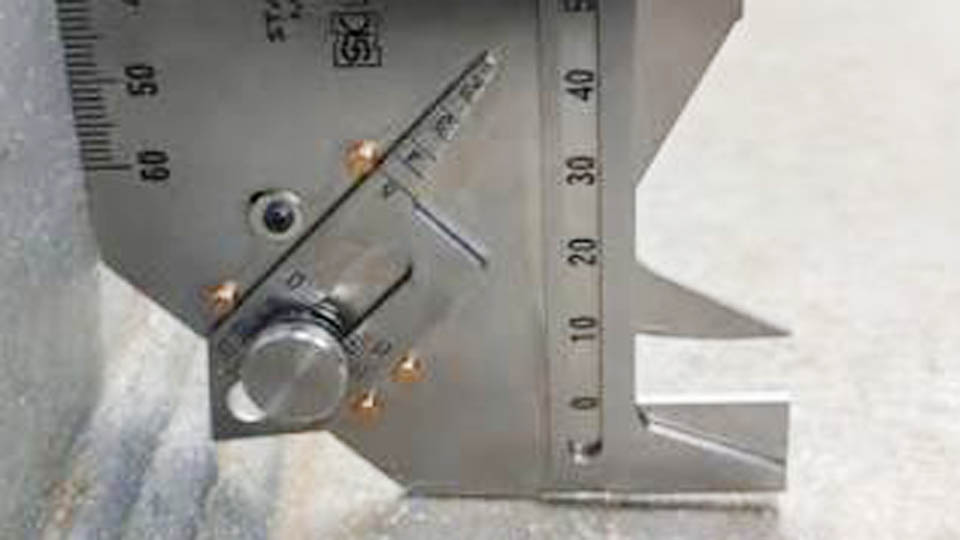
Image by Welding Fabrication World
Understanding Fillet Weld Dimensions and Why Gauges Matter
Leg Length vs. Effective Throat
Fillet weld size is most commonly specified by leg length—the distance from the root to the toe along each fused surface. For equal-legged fillets on 80–100° joints, AWS D1.1 requires this measurement. The effective throat is the shortest distance from the root to the face, measured perpendicular to the hypotenuse of the theoretical isosceles triangle.
A 1/4″ leg fillet theoretically yields about 0.177″ throat (leg × 0.707). In practice, convexity, concavity, or penetration variations alter this. Gauges check both to confirm the weld meets minimum strength without excess reinforcement.
Common Fillet Weld Sizes and Code Minimums
AWS D1.1 Table 7.7 (or equivalent) sets minimum leg sizes based on the thicker part joined:
- Up to 1/4″ thick: 1/8″
- Over 1/4″ to 1/2″: 3/16″
- Over 1/2″ to 3/4″: 1/4″
- Over 3/4″: 5/16″
These ensure adequate heat input and fusion. Maximum size along edges is typically limited to the thinner part thickness minus 1/16″ to avoid melting the corner.
Unequal leg fillets appear in skewed joints or specific load cases. Gauges must verify each leg independently where required.
Gauge Types for Different Applications
Standard blade-style sets (7-, 8-, or 12-piece) offer fixed sizes from 1/8″ to 1″ or larger. Each blade has a cutout for leg measurement and a protrusion for throat/concavity checks.
Adjustable gauges, like the WG-3, use a sliding arm at 45° for continuous measurement from 1/8″ to 1″ in 1/32″ increments, ideal for custom or non-standard sizes.
The AWS-style automatic gauge (or Bridge Cam) combines leg, throat, convexity, concavity, and reinforcement checks in one tool, suiting inspectors handling varied joints.
Choose based on workflow: blade sets for high-volume production checks; adjustable or multi-function for versatility.
Selecting the Right Fillet Weld Gauge for Your Work
Matching Gauge to Material Thickness and Joint Configuration
For thin sheet metal (under 1/4″), prioritize smaller increments (1/16″ or 1/32″). Structural steel fabricators working with 1/2″–1″ plate benefit from sets covering 1/4″–3/4″ most frequently used sizes. Pipe and pressure vessel work often requires checking skewed fillets or T-joints, favoring adjustable models.
Consider environment: stainless steel gauges resist corrosion in marine or food-grade fabrication. Magnetic versions help when working overhead or in awkward positions.
Single vs. Multi-Purpose Tools
Dedicated fillet gauges excel in speed for repetitive tasks. Multi-function gauges (e.g., those measuring undercut, misalignment, or prep angles) reduce kit weight for mobile inspectors or field repairs but may sacrifice some precision on pure fillet checks. Test gauge accuracy against known blocks or a calibrated master before relying on it for critical work.
Budget and Durability Considerations
Entry-level sets suffice for hobbyists, but professionals should invest in etched, hardened stainless models with clear markings. Wear occurs at contact edges; periodic verification against precision blocks maintains reliability.
Preparing for Accurate Measurement
Clean the weld thoroughly with a wire brush or grinder to remove slag, spatter, and scale. Surface irregularities distort readings. Ensure the base metals meet at the expected angle—deviations outside 80–100° require adjusted techniques or different tools.
Verify gauge condition: edges must remain sharp and unmarked. Store in a protective case to prevent bending.
Step-by-Step: Measuring Fillet Weld Leg Length
- Identify the specified leg size from the drawing or WPS.
- Select the matching gauge blade.
- Place the gauge so one edge rests firmly against the vertical member, with the cutout aligning over the weld toe on the horizontal member.
- Slide or position until the gauge contacts the vertical surface fully.
- Check the horizontal toe: the weld should reach or slightly exceed the gauge’s reference line or edge. Gap indicates undersize.
- Rotate to check the other leg by placing the gauge against the opposite surface.
For unequal legs, measure each independently. On larger welds, gravity may produce a larger horizontal leg—acceptable if the vertical leg meets minimum and overall strength is adequate.
The vertical “tip” or edge provides the most accurate leg reference; avoid relying solely on scribed lines if they show wear.
Checking Throat Thickness and Profile
Using the Protrusion for Concavity/Convexity
After confirming leg size, flip the gauge or use the dedicated end. The central protrusion should contact the weld face when legs are correct. Daylight (gap) between protrusion and face signals concavity, reducing effective throat and strength—unacceptable for most structural applications.
Slight convexity is preferred. Excessive convexity wastes material and may indicate poor technique or parameters.
Quantitative Throat Measurement
On AWS-style gauges, position to read the shortest distance from root to face. Compare against 0.707 × leg for theoretical minimum. In practice, aim for effective throat meeting or exceeding code requirements after accounting for profile.
For concave welds, additional passes may be needed to build throat without exceeding leg limits.
Interpreting Results and Acceptance Criteria
AWS D1.1 Tolerances
Undersize allowances exist but are limited: for example, 1/16″ undersize on welds ≤ 3/16″, up to 10% of weld length. Exceeding this requires repair. Oversize is generally permissible unless specified, but excessive material increases costs and heat input.
Convexity limits depend on weld size (e.g., Table 7.9 in D1.1). Concavity is typically not permitted or severely restricted as it reduces throat.
Real-World Decision Points
In production, balance speed and quality. A slightly oversized but convex weld may pass where time is critical, but critical load-bearing joints demand exact compliance. For cyclic loading, profile consistency matters more than marginal size variations.
Document measurements with photos or logs for traceability, especially in certified work.
Advanced Techniques for Complex Joints
Skewed and Unequal Angle Fillets
Adjust gauge positioning to account for actual dihedral angle. Some gauges include scales or arms for non-90° joints. Calculate theoretical throat using trigonometry: throat = leg × cos(θ/2) or similar, where θ is the angle.
Multi-Pass Fillets
Measure after each pass if building large fillets. Intermediate checks prevent defects propagating. Final measurement accounts for cumulative profile.
Pipe and Tubular Applications
Access limitations require smaller or angled gauges. Check around the circumference for consistency, as gravity affects vertical vs. overhead positions differently.
Common Measurement Pitfalls and Corrections
Relying on visual estimation or calipers leads to errors—gauges are designed specifically for the 45° geometry. Worn gauges underestimate size; replace when edges round off. Measuring before cooling fully can give false readings due to contraction.
For very large fillets (>1″), combination of gauge and straightedge or ultrasonic methods may supplement.
Integrating Gauge Use into Workflow
Train welders to self-inspect immediately after welding while the piece is accessible. Supervisors perform spot checks. In QC, 100% verification on critical joints, sampling on others.
Pair with WPS parameters: voltage, amperage, travel speed, and electrode size directly influence achievable consistent sizes. Use gauge data to refine settings.
Maintaining and Calibrating Your Gauges
Clean after each use. Store dry. Periodically compare against certified blocks or a master gauge. Wear beyond 1/32″ typically warrants replacement for precision work. No field recalibration for most blade types—precision grinding is manufacturer territory.
Wrapping Up
Mastering how to use a fillet weld gauge shifts welding from guesswork to engineered precision. Consistent, code-compliant fillets improve joint performance, reduce rework, and build confidence across projects. The next-level insight: in high-performance fabrication, the gauge isn’t just an inspection tool—it’s feedback for parameter optimization.
Welders who correlate gauge readings with their machine settings, technique, and travel speed achieve repeatable quality faster than those relying on post-weld fixes alone. Apply this discipline, and your welds will meet specifications every time.
FAQ
What is the difference between leg length and throat measurement on a fillet weld gauge?
Leg length measures along the joined surfaces from root to toe. Throat measures the perpendicular distance through the weld. Gauges provide quick checks for both, with throat being critical for actual strength.
Can I use a fillet weld gauge on concave welds?
Concave welds fail most acceptance criteria because effective throat is reduced. The gauge’s protrusion will show a gap; add material to correct or rework.
How often should fillet weld gauges be replaced or checked?
Check against known standards before critical jobs. Replace when wear affects accuracy (typically visible rounding or loss of sharp edges). Professional shops calibrate or verify traceability periodically.
Are digital fillet weld gauges worth it?
Digital versions offer convenience for data logging but mechanical gauges remain reliable, durable, and sufficient for most shop needs without batteries or calibration drift concerns.