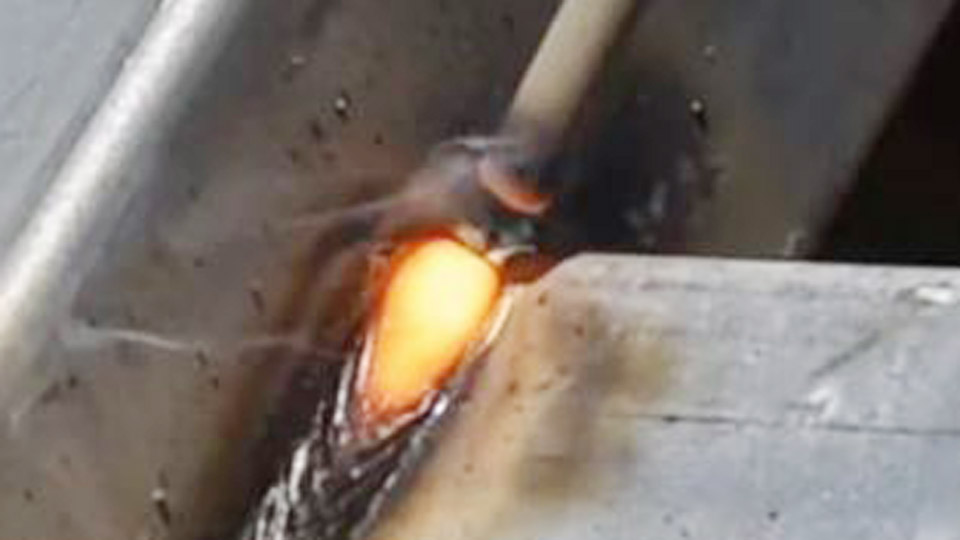
Exhaust pipes demand precise control due to their thin walls—often 1.2–2.5 mm—and exposure to heat cycling, vibration, and corrosion. Many welders struggle with burn-through, weak joints, or leaks when using stick (SMAW) on these materials, especially in field repairs or with limited equipment.
Learning how to weld exhaust pipe with stick provides a portable, gas-free solution for mild steel or select stainless repairs when MIG or TIG isn’t practical.
Success hinges on electrode selection, low amperage settings, heat management, and joint preparation to deliver strong, leak-free results that withstand road conditions.
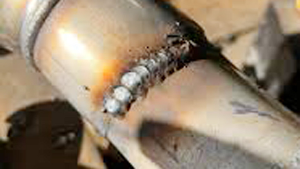
Image by I See You Don’t Know Shit About Welding
Material Considerations for Exhaust Pipe Stick Welding
Exhaust systems use different materials with distinct welding behaviors. Understanding these drives electrode and parameter choices.
Mild Steel vs. Stainless Steel Exhaust Tubing
Mild steel exhaust pipe (typically 14–16 gauge, around 1.6–2 mm wall) offers good weldability but corrodes quickly. It tolerates slightly higher heat input before distortion.
Stainless exhausts (304 or 409 grades, often 1.2–1.8 mm) resist corrosion better but conduct heat differently and risk sensitization or cracking if overheated. Stick welding stainless requires matching or over-alloyed rods and stricter heat control to preserve properties.
Wall thickness dictates feasibility. Below 1.5 mm, stick becomes challenging due to limited arc stability and rapid heat buildup. Aim for butt or lap joints on thicker sections where possible.
Common Thickness Ranges and Challenges
- 1.2–1.6 mm: Demands the smallest electrodes and stitch techniques; high burn-through risk.
- 1.6–2.5 mm: More forgiving with proper settings.
- Flanges and thicker sections (>3 mm): Allow standard rods and higher amps.
Key challenge: Thin walls lose heat slowly in one spot but warp or melt if heat input accumulates. Stick’s intermittent nature helps here compared to continuous processes, but arc starts/stops introduce risks of inclusions or lack of fusion.
Electrode Selection for Exhaust Applications
Electrode choice separates successful repairs from frustration.
Recommended Rods: 6013, 7014, and Alternatives
E6013 (3/32″ or 1/16″) excels for sheet metal and exhaust. It produces a soft arc, easy slag removal, and smooth beads at low amps. Ideal for clean mild steel.
E7014 offers similar usability with slightly better deposition and all-position capability. It runs smoother than 6013 on borderline settings.
E6011 serves dirty or rusty pipes with its digging arc and AC/DC compatibility. It penetrates better but increases burn-through risk on thin material—use sparingly.
For stainless-to-stainless or stainless-to-mild transitions, use E308L-16 or E309L-16 (3/32″). These low-carbon rods minimize cracking. Avoid high-carbon rods on stainless.
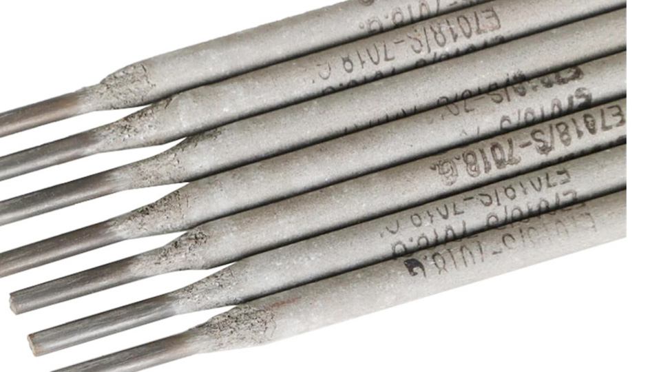
E7018 works for strength on thicker sections but requires dry storage and produces more slag. Less ideal for ultra-thin exhaust due to higher heat needs.
Diameter and Storage Guidelines
Use 1/16″ (1.6 mm) or 5/64″ (2.0 mm) rods for thin exhaust. 3/32″ (2.4 mm) suits 2+ mm walls. Smaller diameters concentrate heat less and allow finer control. Store low-hydrogen rods (7018) in a rod oven or sealed container. Cellulose rods (6010/6011) tolerate more moisture but perform best fresh.
Machine Setup and Amperage for Thin-Wall Pipe
Proper settings prevent most common failures.
Polarity, Amperage Ranges, and Starting Points
- DC Electrode Negative (DCEN/Straight): Preferred for many thin applications as it reduces heat into the workpiece while maintaining arc stability.
- DC Electrode Positive (DCEP/Reverse): Standard for most rods; deeper penetration but more heat.
- AC: Viable with 6011/6013 but less stable on thin material.
Typical ranges (adjust by machine, position, and technique):
- 1/16″ 6013: 25–45 amps
- 3/32″ 6013/7014: 40–70 amps (start low, ~45–55 A)
- 1/16″ stainless rods: Often 10–20% lower than mild steel equivalents
Test on scrap matching your pipe thickness and alloy. Listen for a crisp, frying sound—not popping (too cold) or whooshing (too hot). Fine-tune in 5-amp increments.
Arc Length and Travel Techniques
Maintain a short arc—roughly equal to electrode diameter. Longer arcs increase heat input and spatter. Use a whipping or stitching motion: weld 1/2–1 inch, pause 5–10 seconds for cooling, then continue. This controls the puddle on thin walls and prevents burn-through.
Downhill progression helps on vertical or angled sections by letting gravity assist puddle flow and reducing heat dwell time.
Joint Preparation and Fit-Up
Preparation accounts for 70% of weld success on exhaust.
Cleaning Procedures for Reliable Fusion
Remove rust, scale, paint, and grease to bare metal using a wire wheel, grinder flap disc, or sanding. Wipe with acetone afterward. Contaminants cause porosity or inclusions, especially problematic under exhaust heat and vibration. For old pipes, grind a bevel or clean wider than the final bead width.
Cutting, Alignment, and Tacking Strategies
Use a pipe cutter or abrasive saw for square ends. Deburr thoroughly. For butt joints, achieve near-zero gap. Lap joints (one pipe inside the other) provide more tolerance and easier welding on thin material.
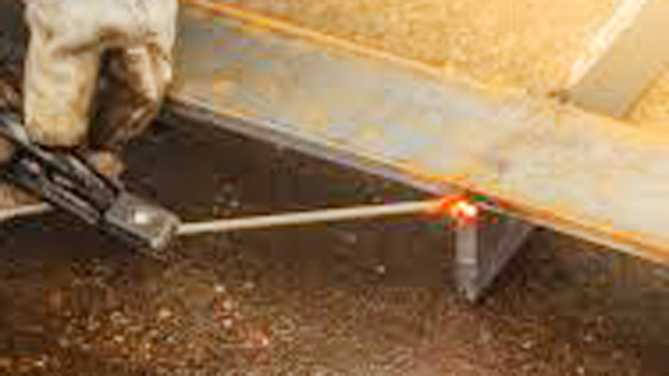
Clamp securely with pipe or chain clamps. Place tacks (quick 1-second arcs) every 90–120 degrees, opposite each other, to minimize distortion. Let each tack cool before the next. Grind tacks lightly before final passes to blend them.
Welding Techniques for Exhaust Pipes with Stick
Focus on controlled execution rather than speed.
Stitch and Skip Welding Patterns
Divide the circumference into segments. Weld short beads (20–40 mm), skip to the opposite side, and repeat. This balances heat input and reduces warping. On a 2-inch pipe, four to six segments per full circle often work. Allow cooling between passes—pipe should be warm, not glowing red.
Position-Specific Approaches
- Flat/Horizontal: Easiest; maintain steady travel with slight circular motion if needed for bead profile.
- Vertical: Weld downhill with 6011/6013. Use faster travel and pause-whip to control puddle.
- Overhead: Challenging on exhaust; minimize puddle size, use smaller rods, and accept potential restarts.
For circumferential welds, rotate the pipe if possible or work in sections.
Multi-Pass Strategies on Thicker Joints
On flanges or repairs over 2.5 mm, use a root pass with 6011 for penetration, followed by fill/cap with 7014 or 7018. Clean slag thoroughly between passes. Overlap beads by 30–50% for full fusion without excessive buildup that could restrict exhaust flow.
Post-Weld Processing and Inspection
Quality doesn’t end at the arc.
Slag Removal and Surface Finishing
Chip slag immediately while warm, then wire brush. Grind flush only where clearance or appearance demands it—reinforcement adds strength on exhaust. Avoid overheating during grinding.
Leak Testing Methods
Pressurize the system (shop air or exhaust) and apply soapy water. Bubbles indicate leaks. Fix by grinding out defects and re-welding. High-temp exhaust paint or ceramic coating protects the weld zone from accelerated corrosion.
Heat Treatment Considerations
Mild steel rarely needs post-weld heat treatment. Stainless benefits from rapid cooling to avoid sensitization, but stick’s low heat usually suffices if you used controlled techniques.
Common Challenges and Parameter Adjustments
Burn-Through Prevention
Lower amps, shorter arcs, faster travel, and more pauses. Backing bars or copper heat sinks (if accessible) help. Switch to lap joints for forgiveness.
Distortion Control
Balanced tacking, skip welding, and clamping. Peen the weld lightly while warm (carefully) to relieve stress on critical sections.
Porosity and Cracking Fixes
Porosity: Better cleaning and shorter arc. Cracking: Match filler strength/chemistry, reduce restraint, and control interpass temperature.
Advanced Considerations for Professional Results
On performance exhausts, consider flow dynamics—avoid excessive protrusion inside the pipe. For dissimilar metal joints (stainless to mild), 309L provides a buffer layer against carbon migration. In high-vibration areas, slightly convex beads resist fatigue better than concave ones.
Track your settings and results for repeatability. Experienced stick welders achieve excellent exhaust repairs, but the process rewards patience and practice on scrap more than most other applications.
Performance-based Takeaway
Stick welding exhaust pipes succeeds through deliberate heat management and material-specific choices rather than brute force. Prioritize 1/16″–3/32″ 6013 or 7014 on DCEN at 30–60 amps with stitch techniques for most mild steel jobs. This yields durable, leak-free joints without specialized gas setups.
The advanced insight: On thin stainless, treat every amp and second of arc time as cumulative damage—master the pause-whip rhythm, and your welds will outlast factory ones in real-world thermal cycling.
FAQ
What amperage should I use to stick weld exhaust pipe?
Start at 35–55 amps with 3/32″ or smaller 6013/7014 rods on 1.6 mm mild steel, using DCEN. Test on scrap and increase only if the arc lacks stability or fusion. Thin stainless often requires even lower settings.
Is stick welding better than MIG for exhaust repairs?
Stick excels in portability, outdoors, or on dirty/rusty pipes without gas. MIG generally offers better control and speed on clean thin material. Use stick when access or conditions limit other processes.
Can you weld stainless exhaust pipe with stick?
Yes, with 308L or 309L rods, low amps, and strict heat control via stitching. It demands more skill than mild steel but produces viable field repairs. TIG remains superior for stainless aesthetics and corrosion resistance.
What rods are best for thin exhaust pipe with a stick welder?
1/16″ or 5/64″ E6013 or E7014 for mild steel. These run smoothly at low amperage with minimal burn-through risk. Avoid 7018 on very thin sections unless you have excellent control.