Many welders struggle with inconsistent penetration, undercut, or excessive spatter because they rely on vague machine dials or guesswork instead of precise amperage settings.
The stick welding amperage chart resolves this by providing electrode-specific ranges that deliver reliable arc stability, proper fusion, and strong welds across mild steel, structural work, repairs, and fabrication.
Correct amperage directly controls heat input, melt-off rate, and bead profile—critical factors that determine whether a joint passes inspection or fails under load.
I’ll discuss the practical, high-density data for DIYers, students, and professionals who need to select the right settings fast and adjust them intelligently for real-world conditions.
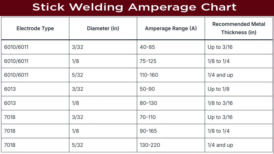
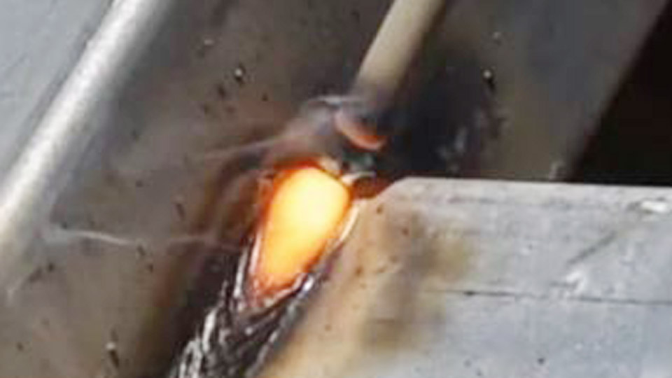
image by garageweld
Understanding Stick Welding Amperage Fundamentals
Amperage governs the amount of electrical current flowing through the electrode and arc. Higher amperage increases heat, accelerating electrode melt-off and deepening penetration into the base metal.
Lower amperage reduces heat, producing a cooler arc suitable for thin materials or out-of-position welding but risking lack of fusion if too low.
Arc Stability and Bead Geometry
At optimal amperage, the arc remains steady with a crisp, consistent crackle. The molten puddle flows smoothly, and slag releases easily.
Too high, and the arc hisses loudly with excessive spatter and a wide, shallow bead prone to undercut. Too low, and the arc stutters, the electrode sticks frequently, and penetration stays shallow with convex beads that trap slag.
Rule of Thumb for Quick Starts
A widely used guideline sets amperage at approximately 1 amp per 0.001 inch (one-thousandth) of electrode diameter. For a 1/8-inch (0.125″) electrode, start near 125 amps and adjust ±10-15 amps based on observed results.
This baseline works across most E60 and E70 series electrodes on mild steel but requires fine-tuning for position, joint type, and polarity.
Manufacturers list ranges on electrode packaging. Always begin in the middle or lower third of the recommended range and test on scrap of identical thickness and material.
Comprehensive Stick Welding Amperage Chart by Electrode Type
The following tables compile real-world amperage ranges for common electrodes. Values assume DC+ polarity unless noted, flat position, and clean mild steel. Adjust downward 10-15% for vertical/uphill or overhead, and upward slightly for thicker sections or multi-pass work.
Cellulose-Coated Electrodes (6010 / 6011)
These deep-penetrating rods excel in root passes, dirty metal, and pipe welding.
- 3/32″ (2.4 mm): 40-85 amps
- 1/8″ (3.2 mm): 75-125 amps
- 5/32″ (4.0 mm): 110-165 amps
- 3/16″ (4.8 mm): 140-210 amps
- 1/4″ (6.4 mm): 210-315 amps (rarely used)
6010 prefers DC+; 6011 runs well on AC or DC.
Rutile-Coated Electrodes (6013 / 7014)
Easy-to-use general-purpose rods with smooth arcs and light slag.
6013:
- 3/32″: 40-90 amps
- 1/8″: 80-130 amps
- 5/32″: 105-180 amps
- 3/16″: 150-230 amps
7014 (iron powder for higher deposition):
- 3/32″: 80-125 amps
- 1/8″: 110-165 amps
- 5/32″: 150-210 amps
- 3/16″: 200-275 amps
Low-Hydrogen Electrodes (7018)
Preferred for critical structural welds due to low hydrogen content and high strength.
- 3/32″: 65-100 amps
- 1/8″: 110-165 amps
- 5/32″: 150-220 amps
- 3/16″: 200-275 amps
- 7/32″: 260-340 amps
- 1/4″: 320-400 amps
7018 performs best on DC+ and requires strict storage to prevent moisture pickup.
Additional Common Types
- 6012: Slightly higher amperage tolerance than 6013 in similar diameters (e.g., 1/8″: 80-140 amps).
- Larger diameters (up to 1/4″) suit heavy plate but demand high-output machines (300+ amps) and multi-pass techniques.
Matching Electrode Diameter to Material Thickness
Electrode diameter should roughly match or stay one size smaller than the plate thickness for single-pass welds. This relationship ensures adequate penetration without burn-through.
Thickness Guidelines
- 1/16″ to 1/8″ (1.6-3.2 mm) thin sheet: 3/32″ or smaller electrodes at 40-90 amps. Use stringer beads and fast travel speed.
- 1/4″ (6.4 mm) plate: 1/8″ electrodes at 100-140 amps typical. Bevel edges for full penetration.
- 3/8″ to 1/2″ (9.5-12.7 mm): 5/32″ or 3/16″ at 140-220 amps. Multi-pass with interpass cleaning.
- Over 1/2″: Larger rods or multiple passes with 3/16″+ electrodes. Preheat may be required on thicker sections to control cooling rates.
Always consider joint design. Open-root joints on pipe need smaller diameters and lower amperage for the root pass, then higher settings for fill and cap passes.
Amperage Scaling with Thickness
For the same electrode size, increase amperage toward the upper end of the range as thickness grows to maintain penetration. On thin material, drop to the lower end and increase travel speed to avoid melt-through. A 10-20% reduction often prevents burn-through on edges or corners.
Position-Specific Amperage Adjustments
Welding position significantly alters heat requirements due to gravity and puddle control.
Flat and Horizontal Positions
Use the full recommended range or slightly higher. Gravity helps the puddle flow, allowing faster travel and higher deposition.
Vertical Uphill Welding
Reduce amperage by 10-15% compared to flat. Smaller puddle size improves control and prevents sag. Example: 1/8″ 7018 at 110-140 amps instead of 120-165. Use a slight weave or whip technique.
Overhead Welding
Drop amperage another 5-10% beyond vertical settings. Focus on short arcs and rapid travel. Larger electrodes become difficult; stick with 3/32″ or 1/8″ maximum.
Vertical downhill (rare for structural work) allows higher speeds but sacrifices penetration—reserve for thin sheet or non-critical applications.
Polarity, Machine Type, and Power Source Effects
DC electrode positive (DCEP/reverse polarity) delivers deeper penetration and is standard for most electrodes. DC electrode negative (DCEN/straight) produces a hotter puddle on the electrode for faster deposition but shallower penetration—useful on thin material with 6013.
AC machines introduce more arc wander but work well with 6011 and 7018. Modern inverter machines provide smoother arcs and better amperage control than older transformers, allowing tighter settings.
Duty cycle matters on smaller machines. Running near maximum output for long periods risks overheating—monitor and allow cooling as needed.
Application-Specific Amperage Strategies
Pipe and Pipeline Welding
Root pass with 6010 (3/32″ or 1/8″) at lower amperage (70-110 amps) for keyhole technique. Hot pass slightly higher, then fill/cap with 7018. Maintain tight control on amperage to achieve consistent root reinforcement without internal protrusions.
Structural and Heavy Fabrication
Favor 7018 or 7014 for productivity. Use 5/32″ or larger where possible on thick sections. Pre-heat thick or high-carbon steels and maintain interpass temperatures. Higher amperage supports larger beads and fewer passes.
Repair and Maintenance Work
Often involves dirty, painted, or rusty metal—6010 or 6011 shine here with their aggressive arc. Start at mid-range and increase if slag inclusion appears. Smaller electrodes help in tight access areas.
Cast Iron and Dissimilar Metals
Lower amperage, smaller diameters, and specialized electrodes (e.g., nickel-based) minimize heat input and cracking risk. Short beads with peening and slow cooling are essential.
Troubleshooting Common Amperage Problems
- Sticking electrode: Amperage too low—raise 5-10 amps or shorten arc length.
- Excessive spatter and undercut: Amperage too high or arc too long—reduce setting and maintain 1/16-1/8″ arc gap.
- Porosity: Check for moisture in low-hydrogen rods or contaminated base metal; amperage alone rarely causes this but extreme settings can exacerbate gas entrapment.
- Lack of penetration: Increase amperage, slow travel speed, or improve joint preparation (beveling, cleaning).
- Burn-through: Lower amperage, increase speed, or switch to smaller electrode. Backing bars help on thin sections.
Listen to the arc and watch the puddle. Experience teaches the ideal “frying bacon” sound and puddle fluidity faster than any chart.
Final Thoughts
Mastering the stick welding amperage chart transforms guesswork into confident, repeatable results. By combining manufacturer ranges, the 1-amp-per-thousandth rule, and position-based adjustments, welders make informed decisions that balance penetration, appearance, and productivity.
The real expertise emerges when you learn to read the arc and puddle in seconds and make micro-adjustments on the fly—separating good welds from code-quality ones.
For critical applications, always verify with test coupons and consider preheat, interpass temperature, and post-weld treatments alongside amperage.
FAQ
What is the best starting amperage for 1/8″ 7018 electrodes?
Start at 110-125 amps on DC+ for flat position mild steel. Adjust based on thickness and position—lower for vertical/overhead, higher for thick plate.
How much should I reduce amperage for vertical welding?
Typically 10-15% lower than flat settings. For example, drop from 130 amps to 110-115 amps for a 1/8″ rod to maintain puddle control without sagging.
Does material thickness change the amperage range for the same electrode?
Yes. Use the lower end of the range for thin material to prevent burn-through and the upper end for thicker sections needing more penetration. Always test on scrap.
Can I use the same amperage settings on AC vs. DC machines?
DC usually allows slightly higher effective heat. On AC, you may need to stay in the middle-to-upper range for comparable results, especially with low-hydrogen rods.