Setting the correct amperage in TIG welding often separates clean, strong welds from burned-through scrap or weak, incomplete fusion. Many welders dial in numbers based on vague memory or machine presets, only to fight inconsistent puddles, excessive heat distortion, or lack of penetration.
A reliable TIG welding amps to metal thickness chart cuts through that confusion by providing starting points tailored to material type, thickness, and joint configuration.
I’ll discuss practical amperage ranges, material-specific adjustments, and decision factors that professionals and serious hobbyists use daily. Master these values to improve consistency across mild steel, stainless, and aluminum.
Understanding Amperage in TIG Welding
Amperage controls heat input and directly influences puddle formation, penetration, and travel speed. Too low, and you get lack of fusion or cold laps. Too high, and you risk burn-through, tungsten contamination, or distortion.
In TIG (GTAW), the relationship follows a rough guideline: approximately 1 amp per 0.001 inch of thickness for mild steel on DCEN. Stainless steel often needs slightly less due to lower thermal conductivity, while aluminum (AC) typically requires more to break through the oxide layer quickly.
Actual settings vary with joint type, fit-up, position, tungsten diameter, filler rod size, and machine characteristics (inverter vs. transformer). Pedal control allows dynamic adjustment, but preset values get you into the effective range fast.
Key Factors Affecting Amperage Selection
Material thermal properties dominate decisions. Mild steel dissipates heat moderately. Stainless retains heat, so lower amps and faster travel prevent warping. Aluminum conducts heat rapidly and needs higher initial amperage plus AC balance and frequency adjustments.
Joint configuration matters equally. Butt joints on thin material use lower settings for controlled penetration. Fillets or T-joints often need 10-20% more amperage for proper sidewall fusion. Open-root joints require precise control to avoid dropping through.
Tungsten electrode size and preparation must match the amperage. A 1/16″ (1.6 mm) tungsten handles roughly 10-150 amps comfortably (sharpened for DC, balled for AC). Exceeding its capacity causes the electrode to overheat and contaminate the weld. Use 3/32″ (2.4 mm) for higher ranges.
Polarity and current type are non-negotiable: DCEN for steel and stainless (focused heat into the workpiece), AC for aluminum (oxide cleaning). Inverter machines often run effectively at slightly lower amps than older transformers.
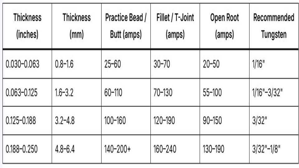
TIG Welding Amps to Metal Thickness Chart for Mild Steel (DCEN)
Mild steel offers the most straightforward starting point. Use these ranges as baselines with argon shielding at 15-20 CFH.
| Thickness (inches) | Thickness (mm) | Practice Bead / Butt (amps) | Fillet / T-Joint (amps) | Open Root (amps) | Recommended Tungsten |
|---|---|---|---|---|---|
| 0.030–0.063 | 0.8–1.6 | 25–60 | 30–70 | 20–50 | 1/16″ |
| 0.063–0.125 | 1.6–3.2 | 60–110 | 70–130 | 55–100 | 1/16″–3/32″ |
| 0.125–0.188 | 3.2–4.8 | 100–160 | 120–190 | 90–150 | 3/32″ |
| 0.188–0.250 | 4.8–6.4 | 140–200+ | 160–240 | 130–190 | 3/32″–1/8″ |
These align with the 1 amp per thou rule while providing headroom. For 1/8″ (0.125″) plate, many welders start near 110-130 amps on a butt joint and adjust via pedal.
Real-world adjustment: On thicker sections or poor fit-up, increase amperage 10-15% and travel faster to manage heat input. Thin sheet benefits from lower settings and pulsing (if available) to minimize distortion.
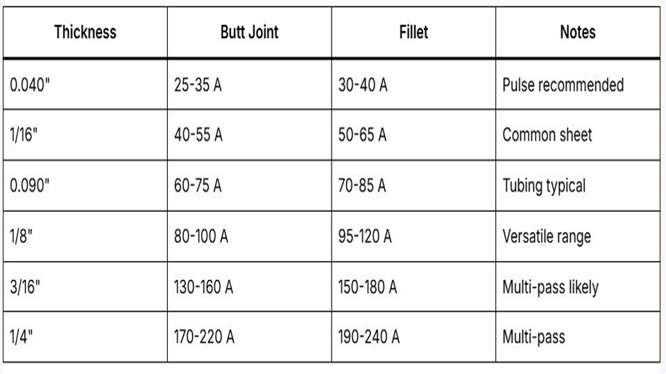
Stainless Steel TIG Amperage Settings
Stainless conducts heat poorly, so amperage runs 10-20% lower than mild steel to avoid excessive heat buildup and sensitization. Cleanliness is critical—oxide or contamination demands higher effective heat, but start conservative.
| Thickness (inches) | Butt Joint (amps) | Fillet (amps) | Tungsten |
|---|---|---|---|
| 0.030–0.063 | 20–55 | 25–65 | 1/16″ |
| 0.063–0.125 | 55–100 | 65–120 | 1/16″–3/32″ |
| 0.125–0.250 | 100–170 | 120–190 | 3/32″ |
Use DCEN with argon or argon-helium mixes for thicker material. Back-purging is often essential on pipe or tanks to prevent sugaring. Travel speed must stay brisk—stainless holds heat longer, increasing distortion risk.
Multi-pass consideration: On sections over 1/4″, layer with controlled interpass temperatures (typically under 350°F) and slightly reduced amperage per pass to maintain properties.
Aluminum TIG Welding Amps Chart (AC)
Aluminum requires higher amperage for rapid puddle formation due to high conductivity and oxide layer. AC balance (typically 60-75% EN) and frequency (80-150 Hz on inverters) influence effective heat.
| Thickness (inches) | Thickness (mm) | Amperage Range | Tungsten (pure or zirconiated) | Filler Rod |
|---|---|---|---|---|
| 0.030–0.063 | 0.8–1.6 | 40–80 | 1/16″ or smaller | 1/16″ |
| 0.063–0.125 | 1.6–3.2 | 70–130 | 3/32″ | 3/32″ |
| 0.125–0.188 | 3.2–4.8 | 110–180 | 3/32″–1/8″ | 1/8″ |
| 0.188–0.250 | 4.8–6.4 | 160–240+ | 1/8″ | 3/16″ |
Start with higher amperage to establish the puddle quickly, then back off. Preheating thick aluminum (200-300°F) reduces required amps and improves fusion. Helium mixes or pure helium boost penetration on thicker sections but narrow the arc.
How Joint Type and Position Change Amperage Decisions
Butt joints demand balanced penetration without dropout. Use the lower end of ranges with good fit-up.
Fillet welds need more heat for leg fusion—add 10-25% amperage compared to flat butt. Vertical-up requires lower settings and faster travel or pulsing to control the puddle. Overhead demands even more skill and often 5-15% reduction to prevent sagging.
Open root vs. closed root: Open roots on pipe use the lowest amperage for controlled keyhole technique. Closed or backed joints allow slightly higher settings.
Thickness transitions: When welding dissimilar thicknesses, set amperage for the thinner piece and direct more arc toward the thicker side.
Tungsten Selection and Amperage Compatibility
Matching tungsten prevents common failures:
- 0.040″–1/16″: Low amperage (<100A), precision work.
- 3/32″: Versatile workhorse (30-200A range).
- 1/8″: High amperage or heavy production.
Pointed tips for DC, rounded/balled for AC. Grind longitudinally to minimize arc wander. Inverter machines tolerate broader ranges than transformers.
Filler Rod Diameter and Amperage Interaction
Filler rod size should roughly match or be one size smaller than tungsten. Thin material (under 1/16″) often uses 1/16″ rod with minimal dipping to avoid overheating. Thicker sections benefit from larger rod for faster deposition without increasing amperage excessively.
Dipping technique affects heat: Frequent small dips on thin material keep heat input low. Larger puddles on thick material accept bigger additions.
Voltage, Travel Speed, and Gas Flow Integration
TIG arc voltage stays low (10-15V) and is relatively stable. Focus on amperage and travel speed for heat input control. Formula: Heat Input (kJ/in) = (Amps × Volts × 60) / Travel Speed (IPM).
Faster travel at higher amps reduces distortion. Gas flow: 15-20 CFH for most cup sizes; increase for larger cups or outdoors. Post-flow 10-15 seconds protects the tungsten and puddle.
Machine Settings Beyond Amperage
Modern inverters offer pulse (e.g., 1-2 Hz for thin material, higher for control), AC balance, and frequency. Pulse reduces average heat input while maintaining penetration—ideal for thin stainless or aluminum. Start with 50-70% peak time and adjust background to 30-50% of peak.
Scaling Amperage for Production and Repair
In repair work, match original material thickness but account for existing heat. Multi-pass thick sections use stringer beads at moderate amperage rather than wide weaves. Production favors automation or higher settings with mechanized travel for consistency.
Decision-Making Framework for Any Job
- Identify base material and exact thickness (use calipers).
- Select polarity/current type.
- Choose tungsten and cup size.
- Reference chart for initial amperage.
- Test on scrap of identical material and joint prep.
- Fine-tune with pedal or pulse while observing puddle fluidity, penetration, and bead profile.
- Record successful settings for future jobs.
This systematic approach eliminates guesswork and builds reliable muscle memory.
Performance-based Takeaway
The best TIG welders treat amperage charts as starting references, not rules. They read the puddle in real time—its size, color, fluidity, and edge wetting—and adjust instantly.
On critical applications, that ability, combined with precise initial settings from a solid TIG welding amps to metal thickness chart, delivers x-ray quality results consistently.
Advanced insight: Once comfortable with these ranges, experiment with helium additions and synchronized pulsing to push travel speeds higher while maintaining superior mechanical properties and minimal distortion.
FAQ
What is the rule of thumb for TIG amps on steel?
Roughly 1 amp per 0.001 inch of thickness for mild steel. Adjust down 10-20% for stainless and up 20-50% for aluminum depending on AC balance. Always verify on scrap.
How do I choose amperage for aluminum TIG welding?
Use higher starting amperage than steel to form the puddle fast (often 1.5–2x the steel equivalent), then reduce. Factor in AC frequency and balance—higher frequency narrows the arc for better control on thicker material.
Does joint type require different amperage in TIG?
Yes. Fillets and T-joints typically need 10-25% more amperage than butt joints for sidewall fusion. Vertical and overhead positions often require reductions to control the puddle.
What tungsten size for 100 amps TIG?
A 3/32″ tungsten handles 100 amps comfortably across most materials. Use 1/16″ for lower ranges or precision, and step up to 1/8″ above 150-200 amps.