Getting aluminum TIG parameters wrong leads to immediate problems—poor penetration, unstable arc starts, excessive heat input, and costly rework. An accurate Aluminum TIG Welding Settings Chart is essential for dialing in amperage, AC balance, frequency, and travel speed based on material thickness and joint configuration.
Aluminum’s high thermal conductivity and oxide layer demand precise control; even small deviations can cause lack of fusion, porosity, or distortion.
This matters on the shop floor where consistency, inspection outcomes, and productivity are directly tied to setup accuracy. Whether you’re working with thin sheet or thicker plate, correct settings reduce burn-through, improve bead profile, and stabilize the arc across varying conditions.
This guide establishes the baseline parameters professionals rely on and clarifies how to adjust them for real-world variables—so you can set up faster, weld cleaner, and minimize defects from the first pass.
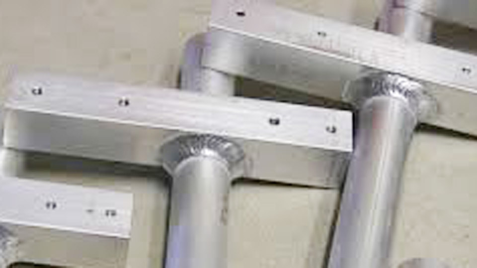
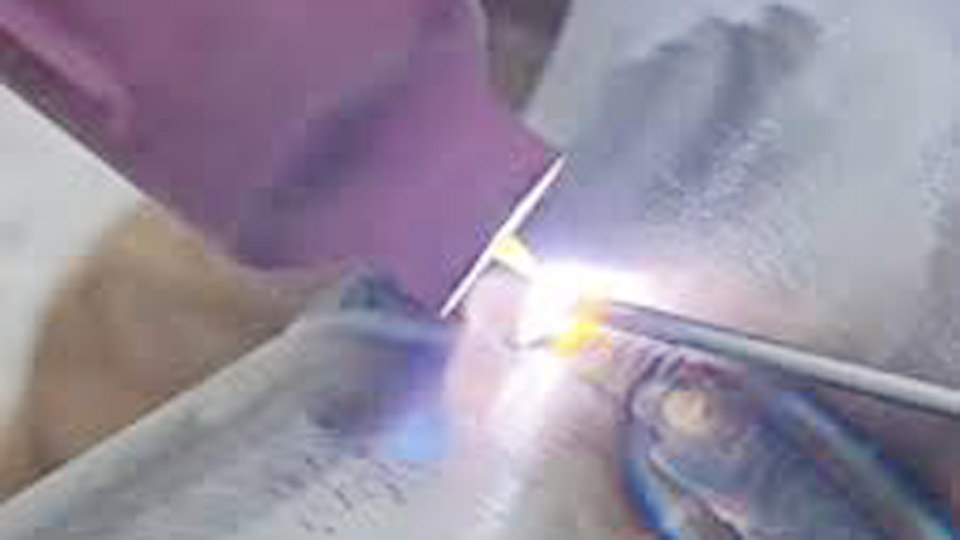
Image by weldingtipsandtricks
Why Aluminum TIG Demands Precise Settings
Aluminum conducts heat rapidly and forms a tough oxide layer with a much higher melting point than the base metal. AC TIG balances cleaning (electrode-positive) and penetration (electrode-negative) cycles, but only the right combination of amperage, balance, frequency, and shielding prevents defects. Wrong settings waste time, material, and tungsten while producing welds that fail inspection or leak in service.
Core Aluminum TIG Welding Parameters by Thickness
Use these as starting points. Always test on scrap of the same alloy, thickness, and joint configuration. Adjust with the foot pedal for real-time heat control.
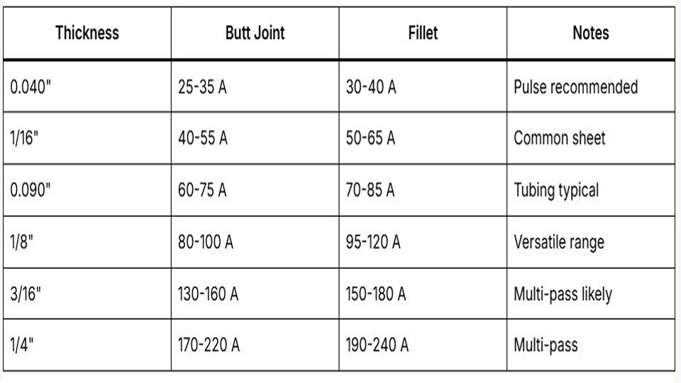
Amperage Guidelines (AC TIG)
Rule of thumb: Approximately 1 amp per 0.001″ of thickness for material up to about 1/4″. Thicker sections often need less relative amperage due to heat buildup, plus joint geometry affects requirements.
- 0.040″ (1 mm): 35–55 A
- 1/16″ (0.063″): 60–85 A
- 3/32″ (0.090″): 80–110 A
- 1/8″ (0.125″): 120–160 A
- 3/16″ (0.187″): 170–230 A
- 1/4″ (0.250″): 220–300 A (preheat often helps)
- 3/8″ and thicker: 280+ A with possible argon/helium mix for penetration.
T-joints or fillets typically require 10–20% more heat than butt joints because heat dissipates in more directions.
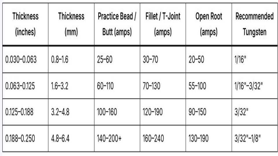
Tungsten Electrode Selection and Preparation
Match tungsten diameter to amperage to maintain a stable arc without overheating:
- Up to 50 A: 1/16″ (1.6 mm)
- 50–150 A: 3/32″ (2.4 mm)
- 150–300 A: 1/8″ (3.2 mm)
- Over 300 A: 5/32″ (4.0 mm) or larger.
Preparation: Use pure tungsten (green) or zirconium (white) for aluminum. Ball the tip slightly—do not sharpen to a point like DC applications. A balled tip stabilizes the AC arc and improves cleaning. Keep the tungsten 1/16–3/32″ above the workpiece for optimal arc control.
Filler Rod Diameter and Alloy Selection
Choose filler diameter roughly matching or slightly smaller than tungsten:
- Thin material (<1/8″): 1/16″ or 3/32″ rod
- 1/8″–1/4″: 3/32″–1/8″ rod
- Thicker: 1/8″–5/32″ rod.
Alloy choice:
ER4043 (5% silicon): Excellent fluidity, lower cracking sensitivity, good for 6xxx series extrusions and general-purpose work. Produces smoother beads but lower strength and ductility. Grayish when anodized.
ER5356 (5% magnesium): Higher strength and better corrosion resistance, preferred for 5xxx series and structural fillet welds. More “sticky” but stronger in shear.
Use 4043 for better flow and appearance on groove welds; switch to 5356 for load-bearing fillets.
AC Balance and Frequency Optimization
Understanding and Setting AC Balance
AC balance controls the percentage of electrode-negative (EN/penetration) versus electrode-positive (EP/cleaning) time.
70–75% EN (25–30% EP): Standard starting point for clean material on modern inverters. Provides good penetration while maintaining tungsten life.
Increase EP (lower EN %): For dirty or oxidized aluminum to enhance cleaning. Watch for tungsten balling or erosion.
Decrease EP (higher EN %): For clean material and maximum penetration. Avoid excessive balling.
Peppering (black flecks) in the puddle signals insufficient cleaning—add more EP. Excessive tungsten heating means too much EP.
AC Frequency Selection
Frequency determines arc cone width and stability:
- 80–120 Hz: Versatile all-purpose range. Good control with decent puddle fluidity.
- Lower frequency (60–100 Hz): Wider arc cone, more heat input, better for thick material or outside corners.
- Higher frequency (150–250 Hz): Tighter, more focused arc for thin material, precise placement, or tight joints. Improves directional control but can sound harsher.
Start at 120 Hz and adjust based on puddle behavior and joint requirements.
Shielding Gas and Torch Setup
Gas: Pure argon for most work. Argon/helium mixes (e.g., 50/50 or 75/25) or pure helium for thick sections (>1/4″) to increase heat input and travel speed.
Flow rates (approximate, use 2–3 CFH per cup size as a guide):
- #5–#6 cup: 15–20 CFH
- #7–#8 cup: 17–25 CFH
- Larger cups or outdoors: Higher flows, consider trailing shield.
Use a gas lens for better coverage and reduced turbulence. Pre-flow 0.2–0.5 seconds; post-flow 10–15+ seconds depending on amperage to protect the tungsten and cooling puddle.
Joint Preparation and Technique Considerations
Clean aluminum thoroughly: degrease, then stainless steel brush or scrape the oxide layer immediately before welding. Oxide reforms quickly.
Travel speed and filler addition: Maintain a consistent speed to avoid heat buildup. Add filler regularly for stacked dimes—more frequent dabs create pronounced ripples by cooling the puddle. Keep arc length short (1/16″ or less) to concentrate heat.
Position-specific adjustments:
- Flat: Highest amperage and fastest travel.
- Horizontal/vertical: Slightly lower amps, slower travel, more filler to control puddle.
- Overhead: Lowest amps in the range, smallest cup, higher gas flow.
Advanced Settings for Specific Applications
Thin Aluminum (<1/8″)
Prioritize heat control to avoid burn-through. Use higher frequency (150+ Hz), lower balance toward more cleaning if needed, and quick foot pedal modulation. Smaller tungsten and cup sizes help focus the arc.
Thick Aluminum (>1/4″)
Preheat (200–300°F) reduces required amperage and cracking risk. Use argon/helium, lower frequency for wider bead, and independent EN amperage if the machine allows (higher EN for penetration while keeping EP moderate).
Pulsed TIG on Aluminum
Pulse settings (e.g., 1–4 PPS) help manage heat on thin or heat-sensitive sections. Peak amps for fusion, background for cooling and control. Useful for root passes or cosmetic work.
Machine-Specific Considerations
Inverter machines run cooler and more efficiently than older transformers, often requiring 10–20% less amperage. Features like independent AC amperage, Pro-Set balance, or waveform control expand the sweet spot. Consult your machine manual for exact balance/frequency labeling (some show % EN, others % cleaning).
Real-World Decision Framework
Match settings to the job:
- Cosmetic/visible welds: Favor 4043, higher frequency, more filler dabs.
- Structural strength: 5356 filler, optimized penetration balance.
- Production speed: Helium mix, pulsed mode, higher travel with proper heat.
- Repair work: Thorough cleaning, preheat on thick castings, test settings carefully.
Always verify with a test coupon. Document successful settings for repeat jobs.
Performance Takeaway
Mastering the Aluminum TIG Welding Settings Chart transforms aluminum from a frustrating material into one that produces reliable, high-integrity welds.
The difference between mediocre and pro-level results often comes down to 10–20 amps, 5–10 Hz, or a few percent balance adjustment—combined with clean metal and steady technique. On critical applications, that precision separates passing welds from those that endure.
FAQs
What is the best AC balance for TIG welding aluminum?
Start at 70–75% EN (25–30% EP) on clean material. Increase EP for oxidized aluminum; decrease for maximum penetration on clean stock. Adjust while watching the puddle for peppering or tungsten condition.
How many amps do I need for 1/8″ aluminum TIG welding?
120–160 A is a solid range. Use the foot pedal to fine-tune. T-joints may need the higher end; test on scrap.
Should I use 4043 or 5356 filler rod for aluminum TIG?
Use 4043 for better flow, appearance, and crack resistance on 6xxx alloys. Choose 5356 for higher strength and corrosion resistance, especially on 5xxx alloys or high-stress fillets.
What gas flow rate is recommended for aluminum TIG?
15–25 CFH depending on cup size (roughly 2–3 CFH per cup number). Use a gas lens for efficiency and increase slightly for larger cups or drafty conditions.