Flow accelerated corrosion (FAC) can silently reduce pipe wall thickness, weaken welded joints, and increase the risk of leaks or unexpected failures in power plants, industrial piping, and process systems.
Understanding How to Prevent Flow Accelerated Corrosion is essential for maintaining weld integrity, reducing costly repairs, and meeting inspection requirements throughout a system’s service life.
FAC develops when high-velocity, low-oxygen fluids gradually remove the protective oxide layer from carbon steel, making material selection, weld quality, flow design, and operating conditions critical factors in long-term reliability.
Effective prevention requires more than routine maintenance—it depends on controlling the conditions that allow corrosion to progress.
I’ll explain the key causes of FAC, practical prevention methods, and engineering practices that help extend equipment life while minimizing downtime, rework, and safety risks.
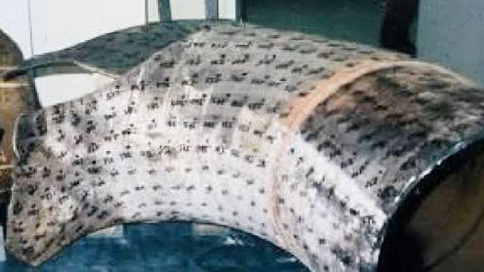
Image by intertek
Understanding FAC Mechanisms in Welded Systems
Electrochemical Dissolution of Magnetite Layer
FAC begins when high-temperature water or two-phase flow dissolves the normally protective magnetite film on carbon steel. The process accelerates under reducing conditions with low dissolved oxygen (DO), typically below 5–10 ppb, and at temperatures around 150–170°C where magnetite solubility peaks. Turbulent flow then removes the weakened or soluble iron species, exposing fresh metal.
In welded piping, the HAZ often exhibits altered microstructure—coarser grains or different carbide distributions—that can increase local dissolution rates compared to base metal. Weld metal chemistry, particularly chromium content, determines whether the oxide layer reforms effectively or remains vulnerable.
Hydrodynamic Influences at Welds and Fittings
Flow disturbances created by weld reinforcements, misalignment, or improper root profiles amplify shear stress and turbulence. These effects concentrate downstream of welds, orifices, and elbows. Single-phase FAC dominates in feedwater lines; two-phase FAC appears in heater drains and low-pressure steam systems where droplet impingement adds mechanical removal.
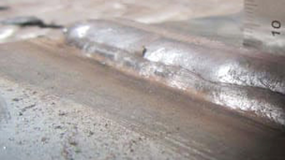
Weld beads protruding into the flow path or undercut create localized eddies that enhance mass transfer coefficients, accelerating thinning rates by factors of 2–5 compared to smooth pipe.
Material Selection and Welding Consumables for FAC Resistance
Chromium Content in Base Metals and Welds
The most effective metallurgical defense is increasing chromium (Cr) levels. Carbon steels with <0.1% Cr suffer high FAC rates, while 0.3–1.25% Cr dramatically improves resistance by enriching the oxide layer with stable FeCr₂O₄ spinel, reducing iron diffusion.
For welding:
- Match or overmatch Cr content in filler metals for low-alloy steels like SA335 P11 (1.25% Cr) or P22 (2.25% Cr).
- Avoid standard carbon steel fillers (e.g., ER70S-6) on Cr-enhanced base metals, as they create galvanic couples or low-Cr zones prone to preferential attack.
- Target weld metal Cr ≥ base metal minimum to prevent downstream acceleration from low-Cr weld metal.
Numerical models show that even small Cr increases in HAZ and weld metal shift thinning locations and reduce rates substantially.
Filler Metal and Process Choices
Select low-hydrogen processes and consumables to minimize HAZ hardness and cracking risks that could compound with FAC. For pipe welding:
- GTAW (TIG) for roots provides smooth profiles minimizing flow turbulence.
- GMAW or FCAW with controlled parameters for fill and cap passes.
- Avoid high-heat-input processes that promote segregation or excessive grain growth in the HAZ.
Preheat (typically 100–150°C depending on thickness and alloy) and controlled interpass temperatures maintain desirable microstructures. Post-weld heat treatment (PWHT) at 600–650°C relieves stresses and homogenizes the oxide-forming capability.
Welding Techniques to Minimize Flow Disturbances
Joint Design and Fit-Up for Smooth Internal Profiles
Poor fit-up creates crevices, misalignment, or protruding roots that initiate localized FAC.
Key practices:
- Use proper bevel angles (typically 30–35°) and root face dimensions for full penetration without excessive reinforcement.
- Employ backing rings sparingly; prefer purge with low-oxygen gas (<50 ppm O₂) for stainless or critical carbon steel to prevent heat tint and oxide defects that reduce corrosion resistance.
- Grind internal weld roots flush or slightly concave where accessible to reduce turbulence. For single-sided welds, control root pass to achieve 0–1.5 mm reinforcement.
Misalignment exceeding 1–2 mm can double local FAC rates due to step changes in flow path.
Weld Profile Control and Post-Weld Finishing
Excessive cap reinforcement or undercut acts as flow obstacles. Maintain weld convexity minimal and grind toes smoothly. In power piping, many codes (e.g., ASME B31.1) limit internal protrusion.
For repairs or modifications:
- Remove existing weld metal completely in affected areas.
- Blend transitions gradually over several pipe diameters to avoid abrupt geometry changes.
- Apply weld overlays with higher Cr content (e.g., 2.25Cr-1Mo) in high-risk zones like downstream of orifices or elbows.
Water Chemistry and Operational Controls Welders Should Support
pH and Dissolved Oxygen Management
Welders cannot control chemistry directly but must understand its interaction with welds. Operate feedwater at pH 9.2–9.8 (adjusted with ammonia or amines) to minimize magnetite solubility. Maintain controlled oxygen levels—5–10 ppb often suppresses FAC better than full scavenging in all-ferrous systems.
Reducing environments from excessive oxygen scavengers accelerate dissolution. Welded systems in mixed-metallurgy plants require careful balancing to avoid copper corrosion while mitigating FAC.
Temperature and Flow Velocity Considerations
FAC peaks near 150°C; avoid prolonged operation in this range if possible through design. Limit velocities: <4–5 m/s in single-phase, lower in two-phase to reduce mass transfer. Welders influence this by ensuring smooth geometries that prevent localized velocity spikes.
During fabrication, document weld locations relative to known high-risk areas (elbows, tees, reducers) for future inspection planning.
Inspection, Monitoring, and Repair Strategies
Non-Destructive Examination Focused on Welds
Implement ultrasonic thickness (UT) mapping prioritizing welds, HAZ, and downstream areas. Use grid scanning rather than spot checks. Advanced techniques like pulsed eddy current or guided wave UT help cover large areas.
Software tools (e.g., those based on EPRI CHECWORKS or similar) predict high-risk locations using flow models, material data, and operating history. Weld documentation feeds these models accurately.
Repair Welding Best Practices
When thinning is detected:
- Excavate damaged material beyond minimum thickness.
- Bevel and prepare joints to sound metal.
- Apply qualified WPS with matching or superior Cr fillers.
- Use stringer beads with controlled heat input to limit HAZ width.
- Perform PWHT where required.
- Verify profile and blend smoothly.
- Conduct post-repair NDE and baseline thickness readings.
Local FAC can accelerate downstream of dissimilar welds due to galvanic or flow effects from differing Cr levels.
Design-Phase Welding Decisions for Long-Term FAC Prevention
Incorporate FAC resistance during new fabrication or refurbishment:
- Specify low-alloy steels (1.25Cr or higher) for high-risk circuits.
- Design piping layouts minimizing turbulence: generous bend radii, streamlined fittings.
- Plan weld placements away from maximum turbulence zones when possible.
- Require internal grinding or lining in critical sections.
CFD modeling during design identifies hot spots; welders execute geometries that match these predictions.
Performance-Based Takeaway
Successful FAC prevention demands integrated decisions: higher Cr materials and fillers for oxide stability, precise welding for minimal flow disruption, and chemistry control tuned to the welded system.
The advanced insight for pros is recognizing that a perfectly executed weld on susceptible carbon steel in a poorly managed chemistry environment will still fail—whereas optimized Cr distribution and smooth profiles extend life even under marginal conditions.
Prioritize Cr content matching and internal profile control on every FAC-susceptible project to deliver piping systems that withstand real operating stresses.
FAQ
What is the main cause of preferential FAC attack near welds?
Altered microstructure and lower Cr content in the HAZ or weld metal compared to optimized base material, combined with local turbulence from weld geometry. Matching Cr and smoothing profiles mitigate this.
Can standard carbon steel welding procedures prevent FAC?
They help minimize defects but are insufficient alone in high-risk systems. Upgrade to Cr-bearing fillers and low-alloy base metals for meaningful resistance.
How does weld reinforcement affect FAC rates?
Protruding beads or misalignment create turbulence that increases mass transfer and local thinning rates significantly. Flush grinding is often essential in critical lines.
What post-weld treatment best supports FAC resistance?
PWHT for stress relief and microstructure tempering, plus thorough surface cleaning/passivation to promote uniform oxide formation. Avoid heat tint through proper purging.