Miller Bobcat 225 Welder Problems can range from hard starting and unstable arc performance to low welding output, engine issues, and electrical faults that interrupt work on the jobsite.
Ignoring these symptoms can lead to poor penetration, inconsistent amperage, excessive downtime, higher repair costs, and welds that fail inspection or require costly rework.
Because the Bobcat 225 is commonly used for field fabrication, repair, and maintenance, identifying the root cause quickly is essential for maintaining productivity and weld quality.
Some problems stem from routine maintenance issues, while others involve the fuel system, engine components, generator output, or welding circuitry. U
nderstanding how these faults affect arc stability and machine performance allows you to diagnose them accurately instead of replacing parts unnecessarily.
I’ll explain the most common causes of Miller Bobcat 225 welder problems and the practical troubleshooting steps that help restore reliable welding performance.
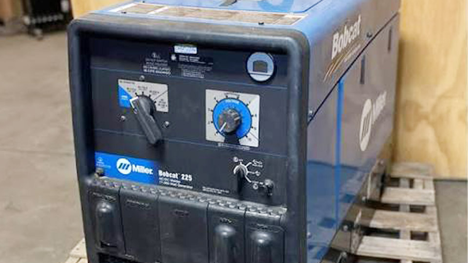
Image by steven_welding_shop
Engine and Starting Failures
Hard Starting or No Crank Conditions
The Kohler or similar engine in the Bobcat 225 requires reliable battery voltage above 12.6V and clean connections for cranking. Low fuel, clogged filters, or a faulty fuel shutoff solenoid commonly prevent starts. Check the 10-gallon tank for fresh, unstale gasoline and inspect the fuel line for kinks or blockages.
For no-crank scenarios, test fuse F6 and verify battery terminals. The low oil pressure shutdown switch can also interrupt operation if oil levels drop or the switch fails. On carbureted models, confirm the choke operates fully and the throttle linkage moves freely without binding.
Engine Runs but Stalls Under Load or at Idle Transition
Idle-to-weld speed transition issues often trace to the auto idle module, current transformer, or throttle solenoid. The engine should ramp to approximately 3600 RPM under weld or generator load. Unstable speeds result from misadjusted governor, dirty carburetor, or vacuum leaks in fuel lines.
Measure fuel pressure (typically 3-5 PSI) at the carburetor inlet. Weak delivery points to a failing fuel pump or restricted filter. Over-revving from stuck throttle solenoids can damage windings—avoid prolonged high-RPM operation without load.
No Weld Output or Generator Power Issues
Complete Loss of Weld and Auxiliary Power
When the engine runs but produces no output, prioritize fuses F1 and F2 (often 25A). These protect the excitation circuit. Blown fuses frequently accompany issues with brushes, slip rings, or rectifiers SR2/SR3.
With the engine off, check rotor resistance across slip rings—target around 3.2 ohms. Higher readings (e.g., 16+ ohms) indicate worn rings or poor brush contact.
Brushes shorter than specification or stuck in holders interrupt field current. Clean slip rings with fine emery cloth (no abrasives that embed) and ensure brush springs provide proper pressure.
Rectifier diodes SR2/SR3 should show 0.4–0.7V forward drop. Failed diodes often crack or overheat. A field flash (momentary 12V DC to the rotor) can restore residual magnetism in some cases, but persistent zero output may require stator or exciter winding inspection.
Weld Output Present but No Auxiliary Power (or Vice Versa)
Separate circuits explain this. Low auxiliary voltage at 120/240V receptacles with good welding often stems from fuse F2, GFCI resets, or receptacle breakers. Full loss of both usually returns to brushes/slip rings or the main excitation path.
Test open-circuit voltage (OCV): expect ~70-80V for DC modes. Verify plug PLG6 connections. Capacitor C1 issues can also affect stability on certain models.
Erratic, Low, or High Weld Output
Weak or Unstable Arc Under Load
Low output under load frequently results from incorrect engine speed (must maintain ~3600 RPM), dirty air cleaner restricting power, or a failing rheostat (R1). The rheostat should sweep smoothly from 0–10 ohms without dead spots.
Range and polarity switches suffer from electrical fretting and arcing, especially in dusty environments. Melted contacts or poor wiper pressure in the coarse range switch commonly kill specific amperage bands (e.g., 70-150A). Disassemble, clean, or replace as needed—grease can attract dirt and accelerate failure.
Excessive or Erratic Output
High output ties directly to overspeed or control settings. Confirm governor adjustment and no linkage binding. Erratic arcs often come from loose weld cable connections, coiled excess cable inductance, or contaminated electrodes. Use dry, properly stored rods and maintain short, clean arcs.
Process-Specific Performance and Settings
Stick (SMAW) Welding Optimization
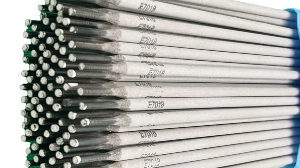
The Bobcat 225 delivers 225A AC or 210A DC at 100% duty cycle (at rated temperature). For 1/8″ 7018 electrodes, select the appropriate coarse range (typically 70-150A or higher) and fine control around 7-10 for smooth beads on thicker material. DCEP polarity yields best penetration; DCEN suits thinner sections or certain electrodes.
Monitor duty cycle closely in hot conditions—exceeding limits leads to overheating and output drop. Poor penetration often traces to low amperage, fast travel speed, or improper joint prep rather than machine faults.
MIG/FCAW (CV Mode) and TIG Setup
In CV mode, set voltage 17-28V with fine control for spray or short-circuit transfer. Use 0.035″ wire with appropriate gas (75/25 Ar/CO2 common). Wire feeders (voltage-sensing or constant speed) pair well, but match inductance and avoid excessive spool gun drag.
For non-critical TIG, AC mode provides good cleaning action on aluminum. DC TIG requires proper polarity and typically lower ranges. Gas flow and tungsten preparation remain critical—machine output stability supports consistent puddles when controls are calibrated.
Simultaneous Welding and Generator Use
Derate outputs when running tools. Peak auxiliary reaches ~11kVA, continuous ~9.5kVA (120/240V). Heavy grinder or light loads reduce available weld amps. Prioritize weld quality by limiting auxiliary draw or alternating loads.
Maintenance Practices for Reliability
Routine Electrical and Mechanical Checks
Inspect brushes and slip rings every 500 hours or at signs of output drop. Clean the generator compartment, tighten all connections, and blow out dust. Test rectifiers and fuses proactively. Replace fuel filters, spark plugs, and oil per engine manual intervals (e.g., oil every 100 hours).
Air cleaner service prevents power loss from restricted intake. Check spark arrestor for blockages in restricted environments.
Advanced Diagnostics and Component Testing
Use a multimeter for diode checks, resistance, and voltage. Rotor/stator continuity and ground isolation tests isolate winding faults. Range switch contact resistance should be near zero. Document baseline OCV and loaded voltages for future comparison. Professional service is recommended for stator or rotor repairs.
Real-World Decision Making
Select replacement parts carefully—OEM fuses, brushes, and rectifiers ensure compatibility. In dusty or high-vibration field use, schedule more frequent switch and brush inspections. For high-duty MIG work, verify CV stability under varying loads. Budget for occasional rheostat or switch replacement as preventive rather than reactive maintenance.
Performance Takeaway
Consistent 225A output and reliable auxiliary power on the Miller Bobcat 225 depend on proactive electrical path integrity—fuses, brushes, slip rings, and switches form the critical chain.
Mastering these diagnostics and settings lets experienced welders maintain full capability on remote sites, minimizing downtime and delivering code-quality welds across processes.
An advanced insight: monitor slip ring resistance trends over time; gradual increases predict brush and output issues long before failure, enabling scheduled intervention that keeps the machine at peak field performance.
FAQ
Why does my Miller Bobcat 225 run but produce no weld output?
Check F2 fuse first, then brush length/contact and ~3.2Ω slip ring resistance. Next inspect SR2 rectifier and rotor windings.
What causes low or erratic auxiliary power on a Bobcat 225?
Reset breakers/GFCI, replace F2 if open, and verify engine RPM (~3600 under load). Clean brushes/slip rings or check rectifiers if voltage remains low.
How do I fix a weak arc or lack of penetration on the Bobcat 225?
Confirm proper coarse range, fine control setting, electrode polarity, and full engine speed. Clean connections, use dry electrodes, and adjust travel speed/heat input.
When should I replace the range switch on a Miller Bobcat 225?
Replace if specific amperage ranges fail, contacts show melting, arcing damage, or high resistance. Common in dusty conditions—clean periodically to extend life.