
Estimating weld time or filler metal usage from memory often produces large errors—jobs finish late, consumable orders fall short, or heat input drifts outside procedure limits.
A reliable weld deposition rate calculator converts electrode or wire parameters into pounds (or kilograms) of metal deposited per arc hour so those estimates become measurable.
Deposition rate directly governs arc time, travel speed selection, and total heat input for a given joint volume. Without accurate numbers, procedure qualification, cost quoting, and shop scheduling rest on guesswork.
The calculations below supply the formulas, efficiency factors, and process-specific ranges needed to generate usable rates for SMAW, GMAW, and FCAW on carbon steel.
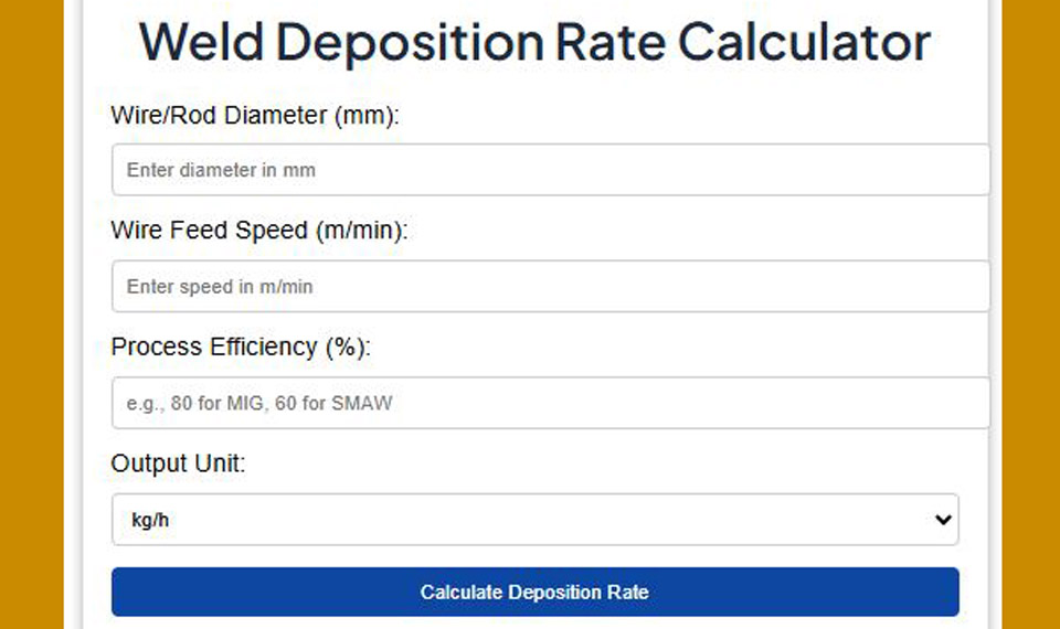
Weld Deposition Rate Calculator
Core Formulas Behind Any Weld Deposition Rate Calculator
Continuous Wire Processes (GMAW and FCAW)
For solid or tubular wire the theoretical melt-off rate starts from geometry and feed speed:
where
- ( D ) = wire diameter in inches
- WFS = wire feed speed in inches per minute
- EE = electrode efficiency (decimal)
The constant 13.1 embeds steel density (0.283 lb/in³) and unit conversion. Equivalent density form:

Typical EE values: solid GMAW wire 0.93–0.98 (spray or pulsed spray near the high end; short-circuit closer to 0.90–0.93); gas-shielded FCAW 0.80–0.90 because flux does not become deposited metal.
Example: 0.045 in ER70S-6 at 350 ipm and 0.95 EE yields approximately 8.7 lb/hr. The same diameter FCAW wire at identical WFS and 0.85 EE drops to roughly 7.8 lb/hr.
Stick Electrode (SMAW) Calculations
SMAW lacks continuous feed, so rates are derived from published burn-off data or empirical equations keyed to amperage and electrode classification. For common low-hydrogen electrodes a linear approximation is used:
E7018-type: DR ≈ (0.012 × A) + 1.0 (lb/hr)
E6010-type: DR ≈ (0.004 × A) + 1.68 (lb/hr)
where A is welding current. At 130 A a 1/8 in E7018 therefore deposits roughly 2.6 lb/hr of weld metal under continuous arc conditions. High-iron-powder electrodes such as E7024 follow steeper slopes and can exceed 4 lb/hr at comparable amperages.
Efficiency for SMAW normally falls between 0.55 and 0.70 after stub loss, slag, and spatter are subtracted; the formulas already embed typical recovery.
How Process Choice Changes Deposition Rate Numbers
SMAW Limits and Real Output
Manual stick welding rarely exceeds 5–6 lb/hr even with large-diameter high-deposition electrodes because operator duty cycle, electrode changes, and slag removal interrupt arc time.
Continuous-arc rates of 2.5–4.0 lb/hr for 1/8 in E7018 at 110–165 A are realistic shop averages once the 30–40 % operator factor is applied. Vertical and overhead positions further reduce usable rate because current must be lowered for puddle control.
GMAW Solid Wire Performance Windows
Short-circuit transfer with 0.035 in wire typically produces 3–6 lb/hr. Spray or pulsed spray on 0.045 in wire at 300–400 ipm routinely reaches 8–12 lb/hr in the flat position.
Raising diameter to 0.052 in at the same feed speeds can push continuous rates above 13 lb/hr, provided the power source and joint geometry support the higher current. Out-of-position work forces a return to short-circuit or pulsed modes and correspondingly lower rates.
FCAW Advantages in High-Deposition Work
Gas-shielded flux-cored wires of 0.045–1/16 in diameter commonly deliver 10–18 lb/hr continuous arc in the flat and horizontal positions. Self-shielded grades sit slightly lower but still exceed most solid-wire GMAW rates at equivalent current.
The tubular design permits higher current density and supports the puddle, which is why structural and shipyard shops favor FCAW when linear feet per shift matter most. Efficiency remains lower than solid wire, so consumable purchase weight exceeds deposited weight by 10–20 %.
Key Variables That Move the Calculated Rate
Wire or Electrode Diameter Effects
Cross-sectional area scales with the square of diameter. Moving from 0.035 in to 0.045 in at fixed WFS multiplies theoretical deposition by approximately 1.65. The same relationship holds for stick electrodes: a 5/32 in rod at its recommended current deposits substantially more metal per hour than a 1/8 in rod.
Larger diameters also raise the minimum stable current, so machine capacity and joint thickness must be verified before the diameter change is made.
Current, WFS, and Transfer Mode Influence
In constant-voltage GMAW and FCAW, wire feed speed is the primary control; current is a dependent variable. Higher WFS increases both deposition rate and heat input. Transfer mode modulates efficiency: spray and pulsed spray recover more metal as weld than short-circuit or globular modes.
For SMAW the independent variable is current; deposition rises almost linearly until the electrode reaches its practical upper limit.
Deposition Efficiency Adjustments
Published rates are continuous-arc values. Real output multiplies by efficiency and by operator factor (arc-on time divided by clock time). SMAW efficiencies of 60 % combined with a 35 % operator factor can cut effective hourly deposition to less than half the continuous-arc figure.
GMAW spray at 95 % efficiency and 50 % operator factor retains far more of the calculated rate. Always apply both factors when converting calculator output into shift productivity or consumable orders.
Converting Deposition Rate into Job Time and Consumable Estimates
Linking Rate to Travel Speed and Joint Volume
Once deposition rate (lb/hr) is known, travel speed follows from required weld-metal weight per unit length:

Weight per inch is obtained from joint cross-section (fillet leg size, groove area plus reinforcement) multiplied by steel density. A ¼ in fillet requires roughly 0.053 lb of deposited metal per foot; at 8 lb/hr the theoretical travel speed is about 15 in/min before any weave or multi-pass adjustment.
Accounting for Duty Cycle and Operator Factor
Calculator output assumes continuous arc. Multiply by the expected operator factor (commonly 0.30–0.40 for SMAW, 0.45–0.60 for semiautomatic GMAW/FCAW) to obtain pounds deposited per clock hour.
Consumable purchase quantity is then deposited weight divided by efficiency. For a 100 lb deposited requirement at 0.85 FCAW efficiency the order must cover approximately 118 lb of wire.
Practical Decision Points When Selecting Settings for Higher Deposition
Larger wire diameter and higher WFS raise rate only when the joint can accept the accompanying heat and when position allows the chosen transfer mode. Flat and horizontal structural fillets favor 0.052 in or 1/16 in FCAW at the upper end of the recommended current range.
Thin-gauge or out-of-position work forces smaller diameters and lower rates to maintain control. When procedure qualification limits heat input, the deposition-rate calculator is used in reverse: fix the maximum allowable heat input, solve for the highest WFS (or current) that still meets the limit, then verify that the resulting rate still meets production targets.
In multi-pass grooves the root pass is frequently run at reduced rate for fusion and profile control, while fill and cap passes are optimized for maximum deposition.
Wrapping Up
Selecting the correct deposition-rate target is a balance between linear productivity and metallurgical constraints. Continuous-arc rates of 8–12 lb/hr with 0.045–0.052 in solid or flux-cored wire represent the practical upper band for most manual and semiautomatic carbon-steel work; higher figures require automation or submerged-arc processes.
Advanced shops treat the calculated rate as an input to heat-input control rather than an independent goal—raising deposition while simultaneously adjusting travel speed keeps the thermal cycle inside qualified limits and preserves toughness in the heat-affected zone.
FAQs
What is a typical deposition rate for 0.045 in ER70S-6 MIG wire?
At 300–350 ipm in spray transfer the continuous-arc rate is approximately 7.5–9 lb/hr before efficiency and operator-factor adjustments.
How do I calculate deposition rate for stick electrodes?
Use the empirical formulas keyed to amperage and classification (for example, E7018 ≈ 0.012 × A + 1.0) or measure electrode weight consumed versus arc time and multiply by the published recovery factor.
Why is FCAW deposition rate higher than solid-wire GMAW at the same current?
Tubular wires support higher current density and the flux system stabilizes the arc, allowing greater wire-feed speeds while still producing acceptable bead profiles.
Does deposition rate include slag and spatter losses?
No. The calculator yields deposited weld metal; efficiency factors must be applied separately to convert melt-off or purchase weight into actual deposited weight.


