
Many welders and fabricators face the same problem after completing critical joints: the code or client requires volumetric nondestructive testing, yet choosing the wrong method leaves dangerous planar cracks undetected or forces unnecessary radiation shutdowns and high costs.
Knowing how to choose between RT and UT directly determines whether porosity clusters, slag, lack of fusion, or tight cracks are found before the part enters service.
RT (radiographic testing) and UT (ultrasonic testing) both examine the full weld volume, but they respond differently to defect shape, orientation, access, thickness, and safety constraints.
Selecting incorrectly can produce false confidence on crack-prone structural welds or inflate inspection time and exclusion zones on high-volume pipe work. The decision rests on matching the physics of each method to the specific defect risks and project constraints.
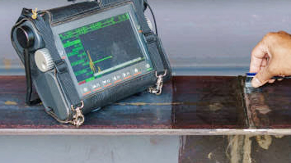
Image by ndtproducts
Which Defects Does Each Method Actually Detect Reliably?
Defect morphology drives the first technical filter. RT and UT interact with discontinuities through fundamentally different physical principles, so probability of detection varies sharply by type.
Volumetric Indications Favor Radiography
Porosity, slag inclusions, and incomplete penetration produce measurable density changes that appear clearly on a radiograph. Gas pockets and slag create darker spots or lines against the denser weld metal.
RT therefore delivers high sensitivity for these volumetric flaws when the radiation beam can pass through the full thickness.
Clustered porosity common in GMAW or SMAW under poor shielding shows up as distinct patterns that are easy to size for acceptance criteria under ASME Section VIII or API 1104.
Planar Flaws Favor Ultrasonic Testing
Tight cracks, sidewall lack of fusion, and laminations present almost no volume change. When oriented nearly parallel to the radiation beam, they produce insufficient contrast and are frequently missed by RT.
UT, especially angle-beam or phased-array techniques, reflects strongly from planar surfaces perpendicular to the sound path.
A lack-of-fusion face along a bevel becomes a high-amplitude echo, and time-of-flight provides accurate through-wall height. Studies comparing the methods consistently show UT superior for planar discontinuities smaller than 1 mm in opening width.
Overlap and Blind Spots
Both methods detect larger volumetric and planar flaws under favorable geometry, yet each has orientation limits. RT can miss cracks aligned with the beam; UT can under-call porosity if the echo amplitude falls below the recording threshold or if the surface is rough.
When both volumetric and planar risks exist—common in multi-pass groove welds—many programs use UT as the primary screen and RT for confirmation on indications.
How Do Access, Thickness, and Geometry Influence the Choice?
Practical constraints often override pure detection capability.
Two-Sided Access Requirements for RT
Film or digital detector placement opposite the source means both sides of the joint must be reachable. Double-wall techniques exist for pipe, but they degrade image quality on thick walls. Complex assemblies, closed vessels, or nozzle-to-shell welds frequently eliminate RT for this reason alone.
Single-Sided Capability of UT
Pulse-echo UT works from one accessible surface. Angle-beam probes interrogate the weld volume by reflecting from the opposite face or by direct path.
This makes UT the default for structural CJP welds on bridges, building frames, and thick plate where the reverse side is obstructed. Phased-array UT further improves coverage by sweeping multiple angles electronically without probe changes.
Thickness Effects
RT remains practical up to roughly 80–100 mm of steel with high-energy sources, beyond which exposure times become excessive. Conventional UT performs well from about 8 mm upward; below that thickness, near-surface resolution suffers and surface methods become more relevant.
For heavy-wall pressure vessels or thick structural members, UT or PAUT often replaces RT because depth sizing remains accurate while radiation logistics grow prohibitive.
What Do Codes and Acceptance Criteria Actually Require?
Code language frequently decides the method before technical preference.
ASME and Pressure Equipment Rules
ASME Section V accepts both RT and UT. Section VIII UW-51 historically centered on RT for butt welds, while UW-53 and Code Case 2235 explicitly permit qualified ultrasonic examination (including PAUT and TOFD) as an alternative when procedures and personnel meet the requirements.
Acceptance criteria differ: RT workmanship standards reject based on length and density of indications, whereas UT can apply fracture-mechanics-based height and length limits that better reflect structural significance.
AWS D1.1 Structural Steel
AWS D1.1 allows either RT or UT for complete-joint-penetration groove welds meeting the thickness and joint-type criteria. Many fabricators prefer UT because it detects the planar flaws that most threaten fatigue performance in cyclically loaded members. Procedure qualification and Level II/III personnel remain mandatory for either method.
API Pipeline and Piping Standards
API 1104 and related pipeline codes historically favored RT for girth welds because of the permanent image record and sensitivity to porosity.
Automated ultrasonic testing (AUT) and PAUT are now widely accepted alternatives, especially on large-diameter, high-volume spreads where speed and radiation exclusion zones become major schedule drivers. Spot RT is often retained on UT indications for characterization.
Always verify the governing code section and any project-specific supplements; assuming interchangeability without documented equivalence leads to rejection at final inspection.
How Do Speed, Cost, Safety, and Record Requirements Compare?
Logistics frequently tip the balance on site or in production.
Cycle Time and Productivity
RT requires source positioning, exposure, processing or digital readout, and interpretation. Typical times range from 45 to 120 minutes per weld once radiation controls are established. Manual UT finishes most welds in 5–15 minutes with immediate results.
Automated systems further reduce unit time on long seams. On a 1,000-weld pipeline project, pure RT can stretch into months while UT screening completes in weeks.
Radiation Controls Versus Acoustic Safety
RT demands licensed personnel, exclusion zones, dosimetry, and often night-shift or isolated work to protect other trades. UT introduces no ionizing radiation and can proceed while other crafts work nearby.
This single difference often makes UT the only feasible volumetric method inside operating plants or crowded fabrication bays.
Permanent Record and Traceability
Film or digital radiographs provide an intuitive visual archive that clients and auditors can review years later. Conventional A-scan UT produces reports and, when required, stored scan data; modern PAUT systems generate C-scans and B-scans that close much of the documentation gap.
When a contract explicitly mandates a radiographic image record, RT remains obligatory regardless of other advantages of UT.
Relative Cost
Once crew size, radiation safety infrastructure, and shot count are included, UT typically runs 50–70 % lower cost per weld than RT for equivalent coverage. Equipment capital for advanced PAUT is higher, yet amortized unit cost still favors ultrasonics on medium-to-high volume work.
When Does a Combined RT-plus-UT Strategy Make Sense?
Critical applications increasingly treat the methods as complementary rather than alternatives.
Screening Plus Confirmation Workflow
UT or PAUT screens 100 % of the welds for planar and volumetric indications at high speed. Any rejectable or borderline echoes then receive targeted RT for permanent image characterization and client approval.
This hybrid approach captures the crack sensitivity of UT and the visual documentation of RT while limiting radiation exposure to a small fraction of the joints.
Fitness-for-Service and In-Service Inspection
UT supplies through-wall height and remaining ligament data required for fracture-mechanics evaluation. RT cannot provide depth information.
Therefore, new-construction acceptance by UT also establishes the baseline for later in-service inspections under ASME Section XI or API 510/570, eliminating the historical mismatch between fabrication RT and operational UT.
Material and Process Specifics
Austenitic stainless steels and high-nickel alloys attenuate ultrasound more than carbon steel and produce grain-noise challenges; RT may retain an edge for volumetric inspection in these materials unless specialized low-frequency or phased-array techniques are qualified. Conversely, thick ferritic welds with high restraint benefit from UT’s planar sensitivity.
Decision Matrix for Typical Weld Inspection Scenarios
| Project Condition | Preferred Method | Primary Reason |
|---|---|---|
| Structural CJP groove, single-side access | UT / PAUT | Planar flaw detection + access |
| Pipeline girth welds, high volume | AUT / PAUT (spot RT) | Speed + crack sensitivity |
| Pressure vessel butt welds needing image record | RT or qualified UT per UW-53 | Code + documentation |
| Castings or complex geometry porosity mapping | RT | Volumetric visualization |
| Operating plant, no radiation allowed | UT | Safety + minimal disruption |
| Fatigue-critical members, crack concern | UT / PAUT | Planar sensitivity + sizing |
| Contract mandates film archive | RT | Permanent visual record |
Match the dominant risk (porosity versus crack), access geometry, schedule pressure, and explicit code language. When both volumetric and planar defects carry equal consequence, the hybrid sequence—UT screen followed by confirmatory RT—delivers the highest overall probability of detection.
Wrapping Up
The correct choice between RT and UT is never universal; it is the combination of defect risk, access, thickness, code language, and operational constraints that selects the method.
Prioritize planar-flaw sensitivity and single-side access with UT or PAUT; prioritize volumetric imaging and permanent visual records with RT.
When the weld is both critical and geometrically complex, sequence the two techniques so each compensates for the other’s physical blind spots.
Advanced programs further integrate real-time process monitoring with targeted NDT, catching instability before the volumetric examination is even required and reducing the total volume of RT or UT needed.
FAQs
Is UT accepted as a full replacement for RT under ASME codes?
Yes, under ASME Section VIII UW-53 and certain Code Cases when the ultrasonic procedure is qualified per Section V and personnel hold the required certifications. Acceptance criteria must be demonstrated equivalent or more conservative than the RT criteria they replace.
Which method is better for detecting lack of fusion in bevel groove welds?
Ultrasonic testing, particularly angle-beam or phased-array techniques matched to the bevel angle, reliably detects sidewall lack of fusion that radiography often misses because of orientation.
Can RT and UT be used together on the same weld?
Yes. A common high-reliability sequence uses UT or PAUT for full coverage screening, then applies RT only to welds showing indications that require visual characterization or permanent image documentation.
Does UT work on thin welds under 8 mm?
Conventional UT loses near-surface resolution below approximately 8 mm. Specialized high-frequency probes or surface methods (MT/PT) become more appropriate; RT remains usable on thin sections if access allows.


