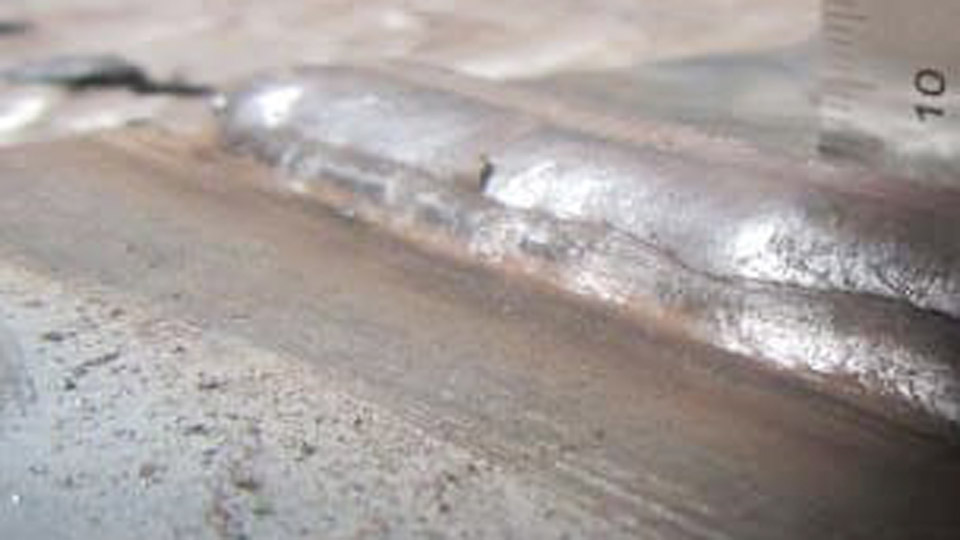
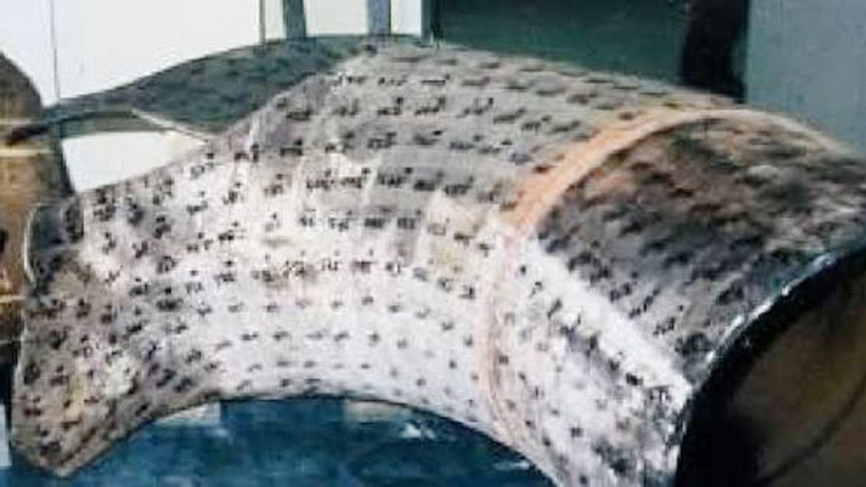
A clean-looking MIG bead that reveals chains of holes after grinding or fails a simple bend test is almost always porosity. Porosity in MIG welding forms when nitrogen, oxygen, or hydrogen dissolves into the molten pool and becomes trapped as the metal solidifies.
The resulting cavities reduce load-bearing cross-section, create stress risers, and frequently cause rejection under structural or pressure-vessel codes. Because the defect can sit just below the surface, visual inspection alone is unreliable.
Identifying the exact gas source—shielding failure, surface contamination, or technique error—lets the welder eliminate the root cause instead of chasing symptoms with higher flow rates or cleaner wire that still produce the same holes.
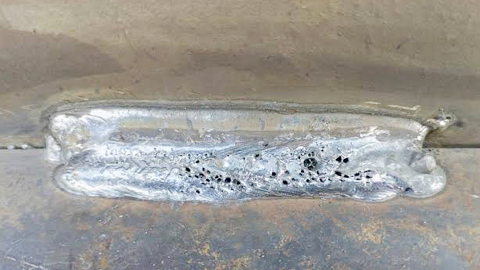
Image by thefabricator
Recognizing Different Forms of Porosity in MIG Welds
Different gas sources produce distinct pore shapes and locations. Matching the appearance to the mechanism speeds diagnosis.
Surface-Breaking Pores and Distributed Porosity
Fine, evenly spaced holes on the bead face or just under a thin skin of metal usually indicate mild atmospheric entrainment. As little as 1 % air mixed into the shielding column is enough to create distributed porosity; above roughly 1.5 % the pores break the surface.
These pores are typically spherical and less than 1 mm in diameter. They appear most often near the toe or centerline when gas coverage is marginally inadequate.
Wormhole or Piping Porosity
Elongated cavities that run perpendicular or at an angle to the weld face produce the classic herringbone pattern on a radiograph. Wormholes form when a large volume of gas is generated rapidly—commonly from thick paint, primer, or heavy oil—and the solidifying front traps the bubbles before they can escape.
T-joints and double-sided fillets are especially prone because the root cavity can act as a reservoir that feeds gas into the pool.
Clustered and Crater-End Porosity
Groups of pores concentrated at the start or stop of a bead often result from abrupt changes in gas flow or from residual moisture on the wire tip.
Crater pipes at the weld termination are a related shrinkage void that frequently contains gas porosity as well. These defects are easier to see but still require complete removal before any repair pass.
Shielding Gas Problems That Create Porosity
Inadequate gas coverage is the single most common cause of porosity in solid-wire MIG. The shielding column must exclude air from the moment the arc starts until the pool freezes.
Correct Flow-Rate Windows by Transfer Mode
Short-circuit transfer on mild steel typically needs 25–35 CFH measured at the nozzle. Spray transfer, which produces a larger, more fluid pool, usually requires 35–50 CFH. Flow rates below these ranges leave the pool exposed; rates significantly above them create turbulence that pulls air into the gas stream.
Always verify flow at the gun, not only at the regulator, because hose restrictions and fittings can drop the delivered volume.
Leaks, Turbulence, and Draft Limits
A cracked O-ring at the gun connector, a loose diffuser, or a kinked hose introduces air long before the flowmeter reading changes. Even a 5 mph draft can displace the shielding column.
In open shops or outdoor work, portable screens that reduce air velocity below 5 mph are more effective than simply raising flow. Excessively high flow itself generates a venturi effect that aspirates surrounding air into the nozzle.
Nozzle Condition and Contact-Tip Recess
Spatter buildup inside the nozzle or on the diffuser ports restricts and distorts the gas pattern. A nozzle that is too small relative to the pool size leaves the edges unprotected. Contact-tip recess (or protrusion) also matters: a tip recessed 1/8–1/4 inch inside a clean nozzle generally gives the most stable gas envelope for short-circuit work.
Excessive stick-out beyond ½–¾ inch moves the arc outside the effective shielding zone and is a frequent porosity trigger.
Base Metal and Wire Contamination Sources
Hydrogen and other gases released from surface films or the filler wire itself produce porosity even when shielding is perfect.
Specific Contaminants and the Gases They Generate
Oil, grease, and cutting fluids break down into hydrogen and hydrocarbons. Rust and mill scale release oxygen and moisture. Zinc coatings and many primers evolve large volumes of vapor that form wormholes, especially in fillet joints.
Moisture on cold plate or in a partially used gas cylinder supplies hydrogen that dissolves readily in the pool. Even “weldable” primers have a maximum dry-film thickness—typically around 20 µm—beyond which porosity becomes probable.
Effective Cleaning Standards Before Welding
Solvent wipe followed by a clean stainless-steel wire brush or light grind to bright metal removes most organic films and light oxide. For aluminum the sequence must be more rigorous: degrease, stainless brush, degrease again, then weld within a short time window because the oxide reforms rapidly.
Wire itself can carry drawing lubricants; if a new spool produces sudden porosity, discard the outer layers or switch brands rather than increasing gas flow.
Technique and Parameter Decisions That Trap Gas
Even with clean metal and correct gas delivery, operator variables can still entrain air or prevent gas escape.
Stick-Out and Contact-Tip-to-Work Distance Limits
Electrical stick-out (contact tip to work) should stay within ⅜–½ inch for most short-circuit applications and ½–¾ inch for spray. Longer distances increase resistance heating, lengthen the arc, and place the pool outside the densest part of the gas column.
Consistent distance is as important as the absolute value; sudden increases at the end of a pass commonly produce crater porosity.
Gun Angle and Travel-Speed Effects
A push angle greater than 15–20° can direct the gas column ahead of the pool and leave the trailing edge unprotected. Excessive travel speed freezes the pool before dissolved gases can rise and escape, locking in fine porosity.
Conversely, extremely slow travel overheats the pool, increases gas absorption, and can create larger cavities. Maintain a travel speed that keeps the arc at the leading edge of a fluid but controllable puddle.
Voltage and Transfer-Mode Interactions
Voltage that is too high for the chosen wire-feed speed lengthens the arc and increases the surface area available for gas absorption. In short-circuit mode this often appears as surface pores; in spray mode it can produce subsurface clusters.
Matching voltage and wire speed so that the transfer mode remains stable reduces the chance of turbulence that mixes air into the pool.
Systematic Diagnosis Sequence When Porosity Appears
When porosity shows up, change one variable at a time in a fixed order to isolate the cause quickly.
Gas-System Verification First
Confirm cylinder pressure, regulator setting, and actual flow at the nozzle. Listen and feel for leaks at every connection from the cylinder to the diffuser. Replace any damaged O-rings or cracked hoses.
Temporarily increase flow 5–10 CFH and weld a test bead; if porosity disappears, the original flow or a minor leak was the problem. If it persists, move to surface condition.
Surface and Wire Checks Second
Grind a fresh test coupon to bright metal, solvent-wipe, and weld immediately. If the new bead is clean, contamination was the source. Inspect the wire for rust, oil, or kinked sections that can interrupt smooth feeding and create momentary arc instability.
Technique and Parameter Isolation Last
Return to the original gas and cleaned plate, then systematically shorten stick-out, reduce gun angle toward vertical, and adjust voltage in 1-volt increments while keeping wire speed constant. Record each change. The combination that eliminates pores becomes the new baseline for that joint and thickness.
Repair Requirements for Porous MIG Welds
Porosity that exceeds code limits or appears in critical load paths cannot be left in place. Surface pores may be acceptable under some structural criteria if their total length stays below stated thresholds (for example, AWS D1.1 limits cumulative porosity in any linear inch and in any 12-inch length). Wormholes and clustered subsurface porosity almost always require removal.
Grind or gouge until every cavity is eliminated and bright, sound metal remains. Clean the excavated area thoroughly, then re-weld using the corrected parameters and gas coverage established during diagnosis.
On multi-pass welds, inspect each layer before the next is deposited; porosity left in a root or fill pass will often propagate into subsequent layers.
Wrapping Up
Correct diagnosis of porosity in MIG welding rests on matching the visible defect pattern to a specific gas source—shielding failure, surface contamination, or technique error—and then verifying the fix with a controlled test bead. Once the responsible variable is isolated and corrected, subsequent welds on the same joint configuration remain free of cavities.
Advanced operators further reduce risk by measuring actual nozzle flow rather than relying on regulator settings alone and by treating every change in wire lot, gas cylinder, or shop draft as a new variable that requires re-verification before production welding resumes.
FAQs
What causes wormhole porosity in MIG welds?
Wormholes form when large volumes of gas—usually from thick paint, primer, oil, or rust—are generated faster than they can escape the solidifying pool. They are especially common in T-joints and double-sided fillets.
What is the correct gas flow rate to prevent porosity in MIG welding?
Use 25–35 CFH for short-circuit transfer and 35–50 CFH for spray transfer, measured at the nozzle. Rates that are too low leave the pool exposed; rates that are far too high create turbulence that pulls in air.
Can porosity in a MIG weld be repaired?
Yes. Grind or gouge out all cavities until only sound metal remains, clean the area, correct the original cause, and re-weld. Leaving porosity in place is unacceptable for most structural or pressure applications.
Why do I still get porosity after cleaning the metal and increasing gas flow?
Check for leaks in the gun, diffuser, or hose; excessive stick-out beyond ½–¾ inch; gun angles greater than 15–20°; and drafts above 5 mph. Any of these can entrain air even when the plate is clean and the flowmeter reading looks correct.