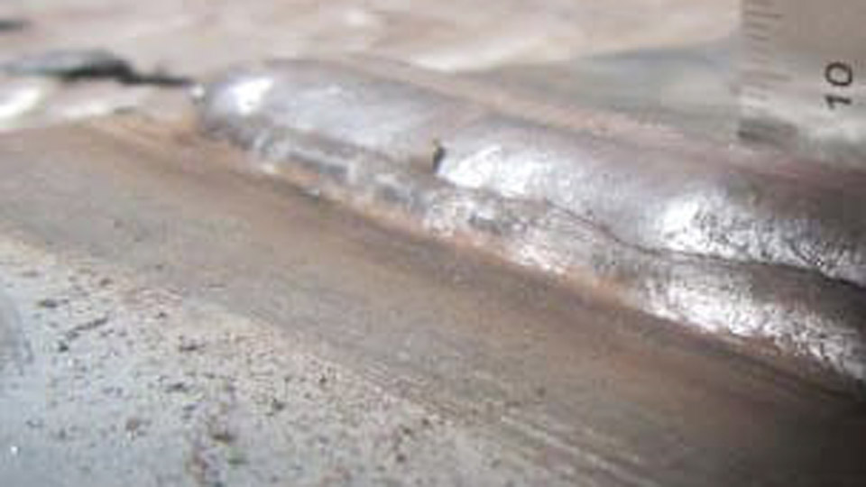
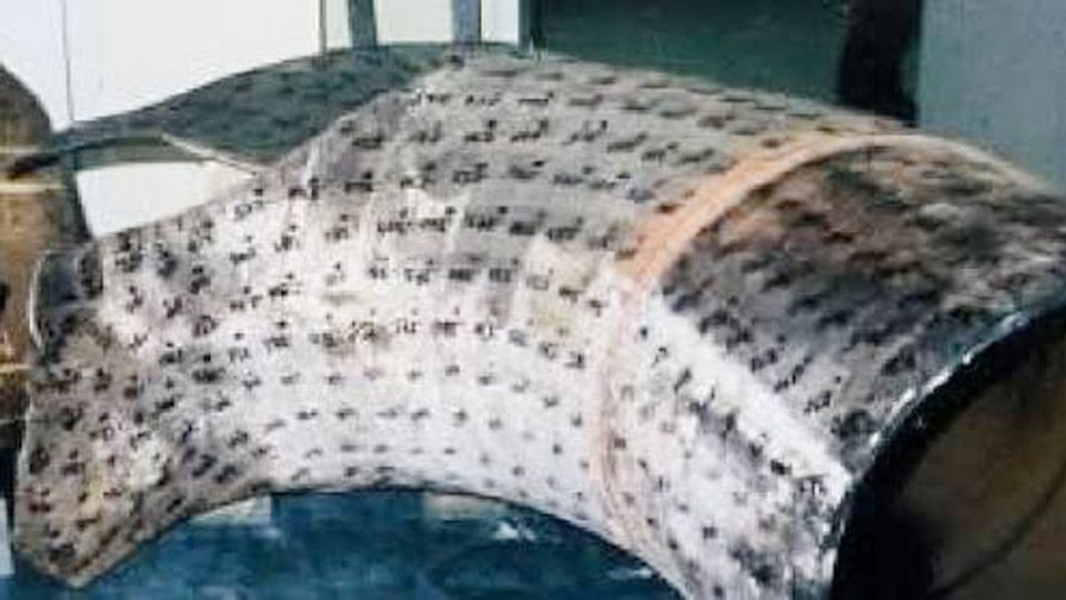
A finished weld that looks acceptable on the surface often hides porosity, undercut, or lack of fusion that only appears under load or during inspection. These problems cost time, material, and structural integrity on everything from hobby frames to code-required joints.
Understanding the 7 common welding defects: causes and expert solutions lets welders diagnose the exact process variable—amperage, travel speed, shielding, joint prep, or consumable condition—before the next pass locks the defect in place.
Correct identification prevents repeated grinding and rewelding cycles that introduce new discontinuities and raise residual stress.
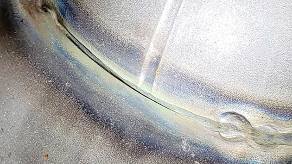
Image by codinter
Porosity: Gas Trapped in the Solidifying Puddle
Porosity forms when gas cannot escape before the weld metal freezes. The cavities reduce load-bearing cross-section and create leak paths in pressure or fluid applications.
Contamination and Moisture Sources
Oil, grease, paint, rust, or mill scale on the base metal generate hydrogen and carbon monoxide that dissolve into the pool. Damp electrodes (especially low-hydrogen 7018) or flux-cored wire exposed to humidity release water vapor that dissociates under the arc. In GMAW and GTAW, moisture in the gas lines or a leaking hose introduces the same gases.
Shielding Failures and Travel Speed
Inadequate gas coverage—flow rates below 15–20 CFH for TIG or 20–25 CFH for MIG, drafts exceeding 5 mph, or a clogged nozzle—allows atmospheric nitrogen and oxygen to enter. Excessively high travel speed freezes the surface before bubbles rise and escape, producing surface pinholes or subsurface wormholes.
Corrective Actions That Eliminate Recurrence
Grind or solvent-clean to bare metal within the joint and HAZ. Store low-hydrogen electrodes in a holding oven at 250–300 °F and recondition only according to manufacturer limits.
Verify gas flow at the nozzle with a flow meter, replace worn liners and O-rings, and reduce travel speed 10–15 % if porosity persists after cleaning. For SMAW, shorten arc length to less than the electrode diameter so the flux can fully shield the pool.
Cracks: Fracture Paths from Stress and Hydrogen
Cracks are the most severe discontinuity because they propagate under cyclic or residual stress. They appear as hot cracks during solidification or cold cracks hours or days later.
Hot Cracking Mechanisms
High sulfur or phosphorus in the base metal, excessive heat input that enlarges the solidification range, or deep, narrow beads that concentrate shrinkage stress produce centerline or crater cracks. High restraint joints amplify the problem.
Cold Cracking and Hydrogen Embrittlement
Diffusible hydrogen from moisture, combined with a hardenable microstructure (CE > 0.40–0.45) and residual tensile stress, drives delayed hydrogen cracks, usually in the HAZ or at the weld toe. Rapid cooling without preheat locks the hydrogen in place.
Parameter and Procedure Fixes
Match filler to base-metal chemistry and use low-hydrogen consumables (H4 or H8 designation). Preheat carbon and low-alloy steels to 100–200 °C (or higher per AWS D1.1 or EN 1011) when thickness or CE demands it.
Fill craters by back-stepping or pausing briefly at the end of each pass. Reduce restraint with balanced welding sequences and allow controlled interpass cooling rather than quenching.
Undercut: Groove at the Weld Toe
Undercut is a continuous or intermittent groove melted into the base metal along the toe and left unfilled. It reduces section thickness and acts as a sharp stress riser.
Heat and Angle Drivers
Excessive current or voltage melts the edge faster than filler metal can replace it. Travel speed too high leaves insufficient time for the pool to wet the toe. An electrode or gun angle that directs the arc primarily at one plate edge concentrates heat on that side.
Process-Specific Adjustments
In SMAW, drop amperage 5–10 % and maintain a 5–15° drag angle. In GMAW, lower voltage 1–2 V or increase wire feed only enough to maintain short-circuit or spray transfer without undercutting.
Slow travel slightly and pause briefly at the toes during any weave so the pool fills the melted edge. On thin material, switch to a smaller-diameter electrode or wire to reduce heat input density.
Lack of Fusion: Incomplete Bonding to Base Metal or Prior Passes
Lack of fusion leaves an unbonded interface between weld metal and base metal or between successive beads. It is often subsurface and requires UT or RT for reliable detection.
Insufficient Heat Input and Access
Low amperage, high travel speed, or an arc that does not reach the sidewalls produces the defect. Tight root openings, excessive land, or poor cleaning of previous slag and oxide layers prevent wetting.
Technique and Joint Corrections
Increase heat input within the qualified procedure range while keeping arc length short. Adjust work angle so the arc energy is directed into both sidewalls and the root. For multi-pass welds, thoroughly chip and wire-brush every interpass surface; any remaining slag or oxide becomes a barrier.
On open-root joints, ensure consistent root gap (typically 1/16–1/8 in for many procedures) and use a slightly higher current on the root pass if penetration is marginal.
Incomplete Penetration: Root Not Fully Consumed
Incomplete penetration occurs when the weld metal fails to reach the required depth through the joint thickness. The unfused root becomes a stress concentrator and leak path.
Fit-Up and Parameter Causes
Root opening too small, land too thick, or bevel angle too narrow restricts arc access. Current too low or travel too fast prevents the pool from melting through the root. Incorrect electrode diameter relative to joint geometry compounds the problem.
Practical Remediation
Increase root opening to the procedure minimum and verify land thickness. Raise root-pass amperage or wire-feed speed enough to achieve a visible keyhole or full melt-through without burn-through.
On thicker sections, consider a back-gouged or back-welded root rather than relying solely on single-sided penetration. Confirm fusion by visual inspection of the root or by radiographic sampling on critical work.
Slag Inclusions: Non-Metallic Trapped Material
Slag inclusions are solid flux or oxide particles trapped inside the weld metal or between passes. They reduce ductility and can initiate cracks under load.
Cleaning and Manipulation Failures
Incomplete removal of slag from the previous pass is the dominant cause in SMAW, FCAW, and SAW. Low current produces a viscous pool that does not float slag to the surface. Wide weaves or steep electrode angles can trap slag under the advancing bead.
Prevention Through Process Control
Chip and brush every pass until bright metal is exposed before depositing the next layer. Raise current slightly within the recommended range to improve slag fluidity and flotation. Maintain a consistent drag angle of 5–15° and avoid excessive weave widths that exceed 2.5–3 times the electrode diameter.
On vertical-up welds, use stringer beads or controlled triangular weaves that allow slag to freeze behind the pool rather than under it.
Excessive Spatter: Metal Particles Outside the Weld
Spatter consists of molten droplets expelled from the arc that solidify on the base metal or fixture. While often cosmetic, heavy spatter indicates process instability that can accompany other defects and increases post-weld cleaning time.
Parameter and Surface Contributors
Excessive voltage or current in GMAW short-circuit transfer, long arc length in SMAW, or contaminated surfaces cause the droplets to explode outward. Incorrect shielding gas mixtures (too much CO₂ without adequate argon) or worn contact tips also destabilize metal transfer.
Stabilization Measures
Lower voltage 1–2 V or adjust wire-feed speed to restore stable short-circuit or spray transfer. Shorten arc length and clean the joint thoroughly.
For SMAW, verify polarity and amperage match the electrode classification; damp or incorrect rods increase spatter dramatically. Anti-spatter compounds can reduce adhesion but do not correct the underlying transfer instability.
Wrapping Up
Decision-making on any of these defects begins with identifying the dominant process variable rather than grinding and rewelding by default. Matching heat input, travel speed, shielding integrity, and joint cleanliness to the specific discontinuity eliminates the root cause and restores mechanical properties.
Advanced practice further incorporates heat-input calculation (kJ/in or kJ/mm) and interpass temperature control so that successive passes do not reintroduce residual stress or hydrogen that converts a surface defect into a propagating crack.