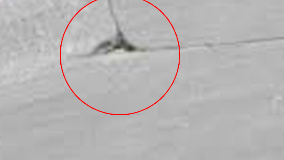
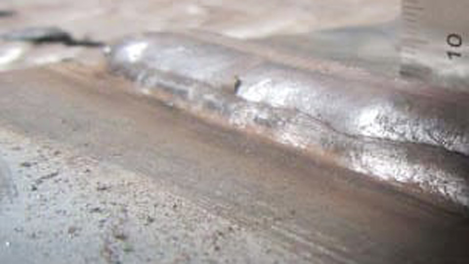
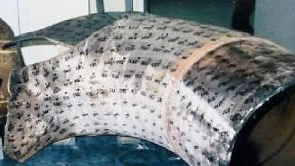
Excess cleanup time after every pass, stuck nozzles, and rejected parts all trace back to the same issue: uncontrolled molten droplets landing outside the intended weld bead. Understanding what is spatter in welding directly affects productivity, joint integrity, and finishing costs.
Spatter consists of small globules of molten filler or base metal ejected from the arc or weld pool during the process. These droplets solidify on the workpiece, fixtures, or equipment, requiring mechanical removal before painting, inspection, or further assembly.
In production environments the cumulative labor and abrasive cost often exceeds the expense of correcting the root parameters that generate the problem.
For structural or code work, heavy spatter can also signal unstable metal transfer that risks incomplete fusion or inclusions if not addressed.
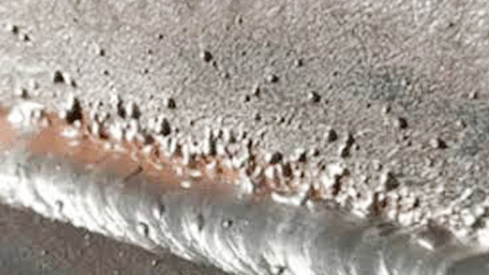
Image by ud-machine
How Metal Transfer Mode Determines Spatter Volume
The dominant factor controlling droplet ejection is the metal transfer mode itself. Each mode produces a distinct arc force and droplet size distribution that either contains or scatters molten metal.
Short-Circuit Transfer Behavior
In short-circuit transfer the wire tip contacts the weld pool repeatedly, extinguishing and re-igniting the arc dozens of times per second. The sudden pinch-off of each short generates a pressure wave that flings small to medium droplets outward.
This mode is required for thin material and out-of-position work, yet it inherently produces moderate spatter unless inductance and voltage are precisely matched to wire diameter. Typical operating windows sit below approximately 22–24 V for 0.035-inch solid wire on mild steel with mixed gas.
Globular Transfer Instability
When voltage or wire-feed speed rises just beyond the short-circuit range without reaching true spray conditions, large droplets (often larger than the wire diameter) form and detach irregularly. Gravity and electromagnetic forces send these oversized globules in random directions.
Globular transfer is the highest-spatter regime and is generally avoided by either dropping parameters back into short-circuit or advancing into spray.
Spray and Pulsed-Spray Stability
True spray transfer detaches a stream of fine droplets smaller than the wire diameter under a continuous arc. The axial transfer path keeps most metal inside the weld pool, reducing spatter to near-zero levels when parameters and gas composition are correct.
Pulsed spray achieves similar droplet control at lower average heat input by alternating peak and background current, allowing out-of-position work with minimal scatter.
Parameter Relationships That Generate or Suppress Spatter
Voltage, wire-feed speed (or amperage), and contact-tip-to-work distance interact continuously. Imbalance in any one variable shifts the transfer mode and raises spatter.
Voltage-to-Wire-Feed Balance
Too-low voltage relative to wire-feed speed causes the wire to stub into the pool, producing explosive short circuits and heavy spatter. Too-high voltage with insufficient wire speed stretches the arc, enlarges the plasma column, and allows larger droplets to form.
The practical decision is to establish a stable arc sound—quiet hiss for spray, controlled buzz for short-circuit—then make 0.5–1 V or 10–20 ipm adjustments while watching droplet behavior on scrap of the same thickness.
Contact-Tip-to-Work Distance Effects
Excessive stick-out increases electrical resistance in the free wire length, effectively lowering current at the arc and promoting colder, more erratic transfer. Insufficient stick-out overheats the contact tip and can cause burn-back. Maintaining ⅜ to ½ inch for most solid-wire applications keeps current delivery consistent and limits unnecessary droplet ejection.
Shielding Gas Composition Trade-offs
Pure CO₂ or high-CO₂ mixes (greater than 25 %) raise arc energy and promote globular tendencies, increasing spatter. Blends containing at least 75–85 % argon enable stable spray transfer on solid wire and markedly reduce droplet scatter.
Metal-cored wires tolerate slightly lower argon percentages while still achieving low-spatter spray. Gas flow rates outside the 20–35 cfh range either entrain air or create turbulence that destabilizes the arc and adds secondary spatter.
Base-Metal and Surface Conditions That Amplify Spatter
Surface condition alters current flow into the workpiece and changes how the molten pool wets.
Mill Scale and Oxide Layers
Hot-rolled steel carries a layer of iron oxides that melt at higher temperatures than the underlying metal. The scale acts as an intermittent insulator, forcing the arc to hunt for clean contact points. The resulting colder, unstable pool balls up rather than wetting out and ejects droplets.
Grinding or using metal-cored wire that can tolerate scale reduces the problem without requiring complete surface removal in every case.
Oils, Coatings, and Contaminants
Hydrocarbons and protective coatings vaporize under the arc, creating gas pockets that explode through the pool surface and carry metal droplets with them. Thorough degreasing and removal of paint or galvanizing in the joint area eliminate this secondary source of scatter. Residual moisture on cold plate or electrodes produces similar steam-driven ejection.
Ground Connection Integrity
A high-resistance ground path causes voltage fluctuations at the arc. The unstable current waveform mimics the effect of incorrect machine settings and elevates spatter. Clean, tight ground clamps placed close to the weld zone keep the electrical circuit consistent.
Process and Consumable Choices That Change Spatter Outcomes
Different welding processes and filler types inherently produce different baseline spatter levels.
Solid Wire versus Metal-Cored Wire
Solid ER70S-6 wire in short-circuit mode generates measurable spatter; the same wire in spray transfer with high-argon gas produces very little. Metal-cored wires carry current primarily through the outer sheath, forming a broader, more stable arc cone that favors axial spray transfer even through light mill scale.
The practical decision is whether deposition rate and reduced cleanup justify the higher consumable cost for the specific joint volume and position.
Stick Electrode Spatter Characteristics
SMAW electrodes produce spatter primarily from coating decomposition and arc force. Cellulosic electrodes (6010/6011) generate more scatter than low-hydrogen 7018 types because of the aggressive gas shield and deeper penetration arc.
Arc length control—keeping the tip nearly in contact with the pool—limits the volume of ejected metal more effectively than amperage changes alone once the electrode is within its recommended range.
Pulsed MIG Capability
Machines capable of pulsed waveforms allow operators to stay in a controlled droplet-transfer regime at average currents suitable for thinner sections or out-of-position work. Peak current detaches a consistent droplet while background current maintains the arc without continuous high heat or large droplet formation.
This approach reduces both spatter and distortion compared with conventional short-circuit or globular regimes.
When Spatter Crosses from Cosmetic to Functional Concern
Not all spatter requires the same response. Decision criteria depend on the acceptance standard and downstream operations.
Visual and Dimensional Requirements
Architectural or exposed structural welds often limit visible spatter by contract. Even small attached globules must be removed before coating systems are applied, because they create high points that paint or powder cannot cover uniformly and can initiate corrosion under the coating.
Potential for Inclusion or Lack of Fusion
Large, loosely attached spatter that is not fully removed before a subsequent pass can become trapped as a solid inclusion. In critical joints this constitutes a rejectable discontinuity under many codes. Thorough interpass cleaning therefore becomes mandatory once spatter volume exceeds light, easily brushed particles.
Equipment and Fixture Damage
Repeated spatter accumulation inside MIG nozzles restricts gas flow and forces premature tip changes. Spatter welded to clamps or fixtures creates fit-up problems on the next assembly.
Preventive measures—nozzle dip, anti-spatter compounds applied only to surrounding surfaces, and routine consumable inspection—protect capital equipment more economically than frequent replacement.
Practical Sequence for Diagnosing and Correcting Excessive Spatter
Begin with the transfer mode required by material thickness and position. Confirm gas type and flow, then verify contact-tip condition and stick-out. Establish a stable arc on scrap of identical chemistry and thickness, adjusting voltage and wire-feed speed in small increments until the arc sound and droplet behavior match the intended mode.
Only after parameters stabilize should surface cleanliness and ground path be rechecked. Anti-spatter compounds remain a secondary defense applied to areas outside the weld zone; overuse inside the joint can introduce porosity.
Selecting the correct combination of transfer mode, gas, and surface preparation determines whether spatter remains a minor cleanup item or becomes a recurring production bottleneck.
Operators who treat spatter volume as a real-time diagnostic of arc stability rather than an inevitable byproduct consistently achieve higher deposition efficiency and lower finishing costs.
Advanced practice further refines this by matching pulse parameters or metal-cored formulations to joint geometry so that the arc itself contains nearly all molten metal within the intended fusion zone.