Welding stainless steel to carbon steel with ER308L often produces centerline cracks or diluted weld metal that loses corrosion resistance.
The higher chromium and nickel in 309 filler wire (ER309/ER309L) compensate for base-metal dilution and maintain a usable ferrite level, preventing those failures in dissimilar joints, overlays, and transition welds.
Selecting the correct 309 variant, polarity, and heat input decides whether the joint survives service or fails under restraint and corrosion.
This guide supplies the composition limits, mechanical values, process parameters, and decision points needed to apply it correctly.
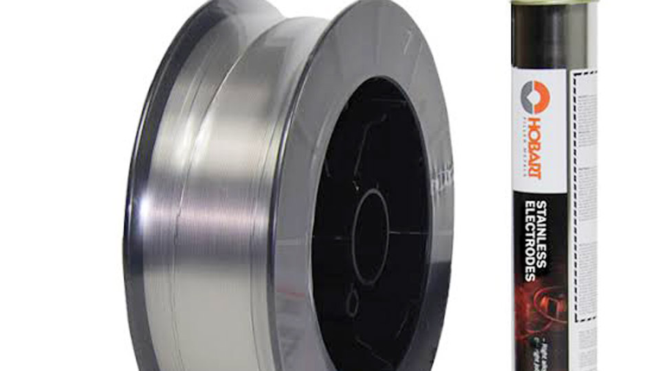
Image by hobartbrothers
When 309 Filler Wire Is Required Instead of 308L or 316L
Dissimilar Joints Between Austenitic Stainless and Carbon or Low-Alloy Steel
ER309L is the standard choice when one member is 300-series stainless (304, 304L, 316, 321) and the other is carbon steel or low-alloy steel. The elevated Cr (23–25 %) and Ni (12–14 %) tolerate iron and carbon dilution from the non-stainless side without dropping below the threshold for hot-crack resistance.
ER308L lacks this margin; dilution routinely pushes the weld metal into a fully austenitic, crack-prone composition.
Buffer Layers and First-Pass Overlays on Carbon Steel
When cladding carbon steel with stainless for corrosion resistance, the first layer must absorb heavy dilution. ER309L supplies the necessary alloy content so subsequent layers of ER308L or ER316L retain proper chemistry. Without the buffer, the final surface can become under-alloyed and sensitized.
Service Temperatures and Unknown Base Metals
309 deposits remain useful up to approximately 700 °F (370 °C) in many applications. For repair work where the stainless grade is unidentified or mixed, the higher ferrite potential of 309 reduces cracking risk compared with matching fillers.
Chemical Composition Limits and Resulting Mechanical Properties
AWS A5.9 Requirements for ER309 and ER309L
| Element | ER309 (max or range) | ER309L (max or range) |
|---|---|---|
| Carbon | 0.12 max | 0.03 max |
| Chromium | 23.0–25.0 | 23.0–25.0 |
| Nickel | 12.0–14.0 | 12.0–14.0 |
| Manganese | 1.0–2.5 | 1.0–2.5 |
| Silicon | 0.30–0.65 | 0.30–0.65 |
| Molybdenum | 0.75 max | 0.75 max |
| Copper | 0.75 max | 0.75 max |
| Phosphorus / Sulfur | 0.03 max each | 0.03 max each |
The “L” grade restricts carbon to minimize chromium-carbide precipitation at grain boundaries during cooling or subsequent heat exposure.
Typical As-Welded Mechanical Values
Tensile strength commonly reaches 85–87 ksi (590–600 MPa). Yield strength falls in the 58–60 ksi (400–415 MPa) range. Elongation is typically 35–40 %.
Ferrite number (FN) in undiluted weld metal usually measures 8–14 by the DeLong or WRC-1992 diagram, providing the ductility needed to accommodate shrinkage stresses in restrained joints.
Effect of Silicon in ER309LSi
Raising silicon to 0.65–1.00 % improves wetting and bead appearance in GMAW spray or pulsed transfer. Mechanical properties remain comparable, though some producers report slightly lower elongation.
MIG (GMAW) Parameter Windows for ER309L Wire
Short-Circuit Transfer on Thin to Medium Sections
Use 0.030″ or 0.035″ wire with tri-mix (90 % He / 7.5 % Ar / 2.5 % CO₂) or argon + 1–2 % O₂. Typical ranges:
- 0.030″: 45–125 A, 15–20 V, wire feed 150–350 ipm
- 0.035″: 60–150 A, 16–22 V, wire feed 120–330 ipm
Stick-out ⅜–½”. These settings limit heat input on 1/16″–¼” material and allow out-of-position work.
Spray and Pulsed-Spray Transfer on Thicker Plate
Switch to argon + 1–2 % O₂ or argon + 2–3 % CO₂.
- 0.035″: 170–295 A, 23–29 V
- 0.045″: 195–360 A, 24–30 V
Travel speed must keep the weld pool fluid enough for complete fusion without excessive reinforcement. Polarity is always DCEP.
Gas Selection Impact on Bead and Spatter
Pure argon produces a sluggish puddle and higher spatter. Adding 1–2 % oxygen stabilizes the arc and improves wetting. Tri-mix increases penetration and is preferred for short-circuit on stainless-to-carbon joints where root fusion is critical.
TIG (GTAW) Settings and Technique Decisions for 309 Filler Rod
Current, Rod Diameter, and Gas Flow
DCEN polarity with 100 % argon. Typical combinations:
| Base Thickness | Rod Diameter | Amperage | Cup Size | Argon Flow |
|---|---|---|---|---|
| 1/16″ | 1/16″ | 80–150 | #6–#8 | 15–20 cfh |
| 1/8″ | 3/32″ | 100–200 | #8 | 20 cfh |
| 3/16″–¼” | 1/8″ | 150–300 | #8–#10 | 20–25 cfh |
Tungsten: 2 % lanthanated or ceriated, ground to a truncated cone. Maintain a short arc length to control dilution on the carbon-steel side.
Root Purging and Backside Protection
On stainless members that will see corrosive service, argon purge the root side to prevent sugaring. Failure to purge leaves a chromium-depleted surface that corrodes preferentially even if the face of the weld meets chemistry requirements.
Heat Input Limits for Multi-Pass Joints
Keep interpass temperature below 300–350 °F on most carbon-steel-to-stainless transitions. Higher interpass temperatures accelerate carbide precipitation and can reduce ferrite content through further transformation.
Managing Dilution and Ferrite Content in Practice
Measuring and Targeting Ferrite Number
Undiluted ER309L deposits 8–14 FN. Heavy dilution from carbon steel can drop FN below 5, raising hot-crack risk. Limit dilution by using stringer beads, low heat input, and, when necessary, a butter layer of pure 309L on the carbon-steel side before joining to stainless.
Buttering Sequence for High-Restraint Joints
Deposit one or two layers of ER309L on the carbon or low-alloy member, machine or grind if required, then complete the joint with the same filler or switch to a matching stainless filler on the stainless side.
This technique isolates the high-dilution zone and is standard practice on pressure-vessel transitions and clad-plate repairs.
When Higher-Ferrite Alternatives Are Preferred
For severely restrained repairs or unknown base metals that crack readily, some shops move to ER312 (FN 20–30). ER309L remains the first choice when service temperature or corrosion requirements rule out the higher-chromium 312 deposit.
Choosing Among ER309, ER309L, and ER309LSi
Carbon Content and Sensitization Risk
Specify ER309L whenever the joint will be exposed to temperatures in the sensitization range (approximately 800–1500 °F) or to corrosive media. The low-carbon limit keeps chromium in solution rather than locked in grain-boundary carbides.
Silicon Level and Process Preference
ER309LSi improves fluidity and reduces the “sticky” puddle characteristic of standard 309L in spray-transfer GMAW. For TIG, standard ER309L is usually sufficient and less expensive.
Cost and Inventory Decisions
ER309L covers the majority of dissimilar and overlay work. Stocking both L and LSi grades is justified only in high-volume MIG production where bead appearance and travel speed justify the premium.
Wrapping Up
Selecting 309 filler wire rests on three technical decisions: the degree of dilution expected from the carbon-steel side, the need for low-carbon resistance to intergranular corrosion, and the process (MIG versus TIG) that dictates silicon level.
When those factors align, ER309L delivers crack-resistant, corrosion-tolerant weld metal that matching 308 fillers cannot provide under the same dilution conditions.
Advanced operators further refine performance by measuring actual ferrite after welding and adjusting heat input or butter thickness so the final FN remains inside the 5–15 window required for both ductility and corrosion resistance.
FAQs
What is 309 filler wire used for?
Primarily for joining stainless steel to carbon or low-alloy steel, for buffer layers before stainless cladding, and for welding 309 base metal itself.
Can I use 309L instead of 308L on 304 stainless?
Yes for non-critical joints, but it is unnecessary and more expensive. 308L matches 304/304L chemistry more closely and is preferred for stainless-to-stainless work.
What shielding gas works best with 309L MIG wire?
Argon + 1–2 % oxygen for spray transfer; tri-mix (He/Ar/CO₂) or the same argon-oxygen mix for short-circuit transfer.
What is the difference between ER309 and ER309L?
ER309L limits carbon to 0.03 % maximum to resist intergranular corrosion; ER309 allows up to 0.12 % carbon and is used where sensitization is not a concern.