Choosing between spot welding and MIG welding depends on the metal thickness, joint design, required strength, and production method. Although both processes join metal through heat, they work differently and serve distinct fabrication needs.
Spot welding uses electrical resistance to fuse overlapping metal sheets at specific points, making it common in automotive body assembly and high-volume production.
MIG welding uses a continuously fed wire electrode and shielding gas to create a weld along a joint, offering greater flexibility for repairs, fabrication, and thicker materials.
Selecting the wrong process can increase production time, cause distortion, or produce joints that do not meet the application’s strength requirements.
Understanding spot welding vs MIG welding helps you determine which method suits your project based on material thickness, accessibility, equipment costs, and weld quality.
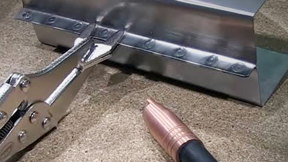
Image by eastwood
Heat Generation and Joint Formation Differences That Drive Strength
Resistance spot welding and MIG create fundamentally different fusion zones, which directly controls how the joint carries load.
Resistance Heating and Nugget Formation in Spot Welding
Spot welding clamps overlapping sheets between copper-alloy electrodes and passes high current (typically 6–15 kA for mild steel sheet) for a short time measured in cycles (1 cycle ≈ 1/60 s on 60 Hz power). Contact resistance at the faying surface generates localized heat that melts a lens-shaped nugget.
Electrode force (commonly 2–6 kN) forges the molten metal while it solidifies. No filler is added. Nugget diameter is usually targeted at roughly 4–5 √t mm (t = thinner sheet thickness in mm). On 1.0 mm mild steel the process often runs 9–11 kA, 10–12 cycles weld time, and 2.5–3.5 kN force.
Arc Melting and Continuous Fusion in MIG Welding
MIG maintains a continuous arc between a consumable wire electrode and the workpiece under shielding gas. Heat input is controlled by amperage, voltage, wire-feed speed, and travel speed. On 1.0–1.2 mm sheet, short-circuit transfer typically uses 60–100 A with 0.023–0.030 in wire; on 3.2 mm plate the range rises to 125–175 A with 0.035 in wire.
The process deposits filler and can produce full-penetration butt or fillet joints. Penetration depth scales with current and can reach the full thickness of the base metal when parameters and joint preparation allow.
Load-Type Implications of Discrete Nuggets Versus Continuous Beads
A properly sized spot-weld nugget develops high shear strength—often matching or exceeding the base-metal shear capacity of the sheet. Multiple spots spaced 20–40 mm apart transfer load effectively in automotive body structures.
Under peel or tensile loading the discrete nuggets are less efficient; continuous MIG beads distribute stress more evenly and generally show better fatigue performance on structural seams. For thin lap joints under pure shear, spot welds frequently outperform equivalent MIG plug welds in both quasi-static and dynamic tests.
Thickness Limits and Joint Geometry Constraints
Material thickness and joint design eliminate one process or the other before any other factor is considered.
Practical Thickness Windows for Reliable Spot Welds
Spot welding performs reliably on single-sheet thicknesses from approximately 0.5 mm to 1.5–2.0 mm (total stack up to about 3 mm). Above that range, required current and force climb rapidly, electrode indentation increases, and consistent nugget formation becomes difficult without industrial water-cooled equipment.
Galvanized or high-strength steels need higher current (often +10–20 %) and more frequent electrode dressing because coatings raise contact resistance and accelerate tip wear.
MIG Thickness Range and Joint Flexibility
MIG covers from thin sheet (with short-circuit or pulsed modes) to plate exceeding 25 mm via multi-pass techniques. It accepts butt, fillet, lap, T, and edge joints and tolerates modest gaps that spot welding cannot bridge.
On auto-body gauge material, MIG plug welds or stitch seams are used when electrode access is blocked or when the OEM procedure specifies continuous fusion.
Access Requirements That Override Other Considerations
Spot welding demands electrode access to both sides of the lap. Closed sections, boxed structures, or one-sided repairs force a switch to MIG (or another process). MIG torch access is more flexible, though still limited by joint location and fixture interference.
Equipment, Consumables, and Operating Cost Reality
Capital and running costs differ sharply once volume and joint mix are known.
Spot Welder Power and Electrode Demands
Shop-level spot welders range from single-phase 220 V units suitable for light body work to three-phase or inverter machines with digital timers and force control. Electrodes (Class 2 copper-chromium for mild steel) require periodic dressing to maintain face diameter and contour.
No shielding gas or filler wire is consumed. Cycle times of 0.5–2 seconds per spot make high-volume panel work efficient.
MIG System Components and Ongoing Consumption
A functional MIG setup includes a constant-voltage power source, wire feeder, torch, and gas cylinder or bulk system. Typical mild-steel gas is 75 % argon / 25 % CO₂ at 15–25 cfh. Wire consumption runs 1–2 lb per hour of arc time depending on diameter and parameters.
Spatter cleanup and tip replacement add labor. Entry-level 180–250 A machines handle most fabrication and repair; higher-output units support thicker structural work.
Cost Trade-Offs at Different Production Scales
On repetitive thin-gauge lap joints, spot welding reduces consumable and finishing cost dramatically. On mixed-thickness or multi-joint fabrications, MIG’s versatility offsets its higher consumable burn rate. Many body shops and job shops maintain both processes precisely because neither covers the full range of work efficiently alone.
Distortion, Appearance, and Heat-Affected Zone Control
Heat input profile determines panel flatness and post-weld finishing effort.
Localized Heat Cycle of Spot Welding
The brief, concentrated energy pulse produces a small heat-affected zone. Distortion on 18–20 gauge auto-body panels stays minimal when electrode force and current are balanced. Surface marks are small and often require only light dressing. Factory-style appearance is preserved when spacing matches OEM patterns.
Continuous Heat Input and Warpage Risk with MIG
Even with short-circuit transfer and high travel speeds, the continuous arc deposits more total energy along a seam. Thin panels can warp unless stitch techniques, backing, or clamps are used. Plug welds still require grinding to achieve a flush surface, increasing labor and the chance of thinning the surrounding metal.
Practical Distortion Management Decisions
When panel flatness and corrosion-coating integrity matter most (outer body panels, visible flanges), spot welding is preferred if access allows. When the joint must be continuous or the section is structural and thicker, MIG parameters are tuned for lowest practical heat input and the resulting distortion is accepted or corrected mechanically.
Decision Criteria for Shop and Production Environments
A short checklist based on joint requirements selects the correct process in most cases.
Conditions That Favor Spot Welding
- Overlapping sheets ≤ 1.5–2 mm each
- Both-side electrode access
- High volume of identical lap joints
- Priority on low distortion and minimal finishing
- Shear-dominated loading with proper spot spacing
Conditions That Favor MIG Welding
- Any non-lap joint geometry or gaps > 0.8 mm
- One-sided access only
- Thickness beyond reliable spot range
- Continuous seams or structural load paths requiring full penetration
- Mixed materials or repair situations where filler is needed to restore section
Hybrid Approaches Common in Practice
Automotive repair frequently combines both: resistance spots on accessible flanges and MIG plug or stitch welds where access or procedure demands it. Production lines may use robotic spot welding for body-in-white and MIG for sub-assemblies that require continuous beads.
Parameter validation on sample joints (nugget diameter peel tests for spot, bend or tensile tests for MIG) confirms the chosen schedule before production.
Parameter Starting Points That Avoid Common Defects
Correct settings prevent expulsion, undersized nuggets, burn-through, and incomplete fusion.
Representative Spot-Welding Schedules for Mild Steel
For two equal-thickness bare mild-steel sheets on a typical AC machine:
| Thickness (each) | Force (approx.) | Current | Weld Time (cycles) |
|---|---|---|---|
| 0.8 mm | 2.2–2.5 kN | 9 kA | 8 |
| 1.0 mm | 2.5–3.0 kN | 9.5–10.5 kA | 10 |
| 1.2 mm | 2.8–3.5 kN | 10–11 kA | 12–13 |
| 1.5 mm | 3.5–4.0 kN | 10.5–11.5 kA | 14–15 |
Galvanized steel usually requires 10–20 % higher current and more frequent tip dressing. Hold time after current ends allows the nugget to solidify under pressure.
Typical MIG Settings for Comparable Sheet Work
On 1.0–1.2 mm mild steel with 0.030 in ER70S-6 wire and 75/25 gas: 70–100 A, 16–19 V, wire-feed speed matched to current, short-circuit transfer, travel 12–20 ipm. Increase current and switch to spray or pulsed modes as thickness rises. Always verify gas coverage and contact-tip-to-work distance.
Wrapping Up
The choice between spot welding and MIG welding is settled by matching process physics to joint demands rather than by preference or equipment ownership. Thin overlapping sheet under shear with two-sided access belongs to resistance spot welding for speed, low distortion, and zero filler cost.
Continuous seams, thicker sections, gaps, or one-sided access belong to MIG for penetration and joint versatility.
Advanced shops treat both as complementary tools: they validate nugget size or bead profile on the actual material and coating, then lock the schedule so every joint meets the required mechanical and appearance targets without excess heat or consumable waste.
Wrapping Up
Is spot welding stronger than MIG welding on sheet metal?
On thin lap joints under shear, a correctly sized spot-weld nugget often equals or exceeds the shear strength of a comparable MIG plug weld and shows superior performance in some dynamic tests. Continuous MIG seams generally provide better tensile and fatigue performance on structural joints.
Can I use MIG instead of spot welding for auto body panels?
Yes when access prevents electrode reach or the repair procedure specifies plug or stitch welds. Expect more heat, possible distortion, and additional finishing compared with properly executed resistance spots.
What thickness is too thick for spot welding?
Above roughly 1.5–2 mm per sheet (total stack ≈ 3 mm) consistent nuggets become difficult on standard shop equipment; industrial machines can go higher but force and current demands rise sharply.
Do I need shielding gas for spot welding?
No. Resistance spot welding generates heat internally between the sheets and requires neither filler metal nor shielding gas.