Freehand plasma cuts on complex shapes produce wandering edges, inconsistent kerf, and parts that never fit. A reliable set of patterns for plasma cutter work—whether physical templates or clean digital files—removes that variability by locking torch path, lead-in points, and kerf offsets before the arc starts.
Correct patterns determine whether holes stay round, external profiles meet tolerance, and nested sheets waste the least material. Without them, even a properly tuned 40–60 A machine on 1/8-inch plate delivers tapered edges, excess dross, and rework that doubles shop time.
Pattern choice and preparation control every downstream decision: amperage, travel speed, consumable selection, and final fit-up.
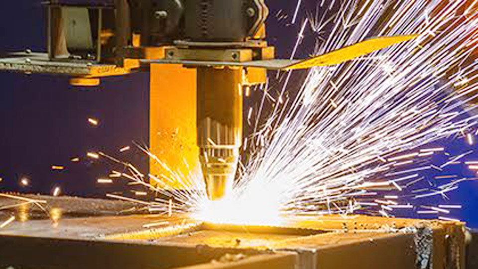
Image by red-d-arc
Choosing Between Physical Templates and Digital Cut Files
The decision starts with the equipment and production volume. Handheld torches rely on physical guides; CNC tables require vector files ready for CAM.
When Physical Templates Deliver Better Control
Physical templates work best for one-off or low-volume parts on handheld plasma. Material thickness of the template itself should run about 1/4 inch so the drag tip or standoff guide has a firm vertical face. Cardboard or poster board suits single-use work; phenolic, acrylic, or thin aluminum lasts through dozens of cuts.
The template outline must already include the tip radius offset—typically half the consumable diameter plus a small clearance—so the finished edge lands on the design line.
Clamp both template and workpiece to the table on supports that allow the plasma jet to exit freely; any obstruction under the cut line forces molten metal back into the kerf.
When DXF or SVG Files Become Mandatory
CNC plasma tables require closed-contour vector files. DXF remains the most universal format because nearly every CAM package imports it without conversion loss. SVG works when the software accepts it, but scale and unit checks are still required.
Files must contain only clean geometry: no open contours, zero-length segments, or duplicate lines. Those defects abort the cut or produce incomplete paths. Layers that separate external profiles, internal holes, and marking lines simplify toolpath assignment and reduce programming errors.
Kerf Compensation Rules That Keep Parts on Size
Plasma removes a measurable band of metal. Ignoring that band produces undersized external parts and oversized holes.
Measuring Actual Kerf on Your Machine
Cut a test square or rectangle from the same material and thickness at the exact amperage, speed, and height you will use for production. Measure the finished dimension with calipers. The difference between designed size and measured size equals total kerf.
Typical values for air plasma on mild steel fall between 0.8 mm on thin gauge at low current and 2.5 mm on 1/2-inch plate at higher amperage. Half that value becomes the offset applied in CAM: outward for external profiles, inward for holes and slots.
Applying Offset Direction Correctly
External profiles shift the toolpath outward so the kerf sits in the scrap. Internal features shift inward so the kerf sits in the waste that falls out. Reversing the direction produces parts that are systematically oversized or undersized by a full kerf width.
Minimum feature size must stay larger than the kerf—generally 1.5 to 2 times kerf width for reliable holes and webs. Thin bridges narrower than that collapse or leave incomplete cuts.
| Plate Thickness | Typical Kerf (Air Plasma) | Minimum Web / Bridge | Lead-in Length |
|---|---|---|---|
| 1–3 mm | 0.8–1.2 mm | 5–6 mm | 1.5–2 mm |
| 4–6 mm | 1.2–1.5 mm | 6–8 mm | 2–3 mm |
| 8–10 mm | 1.5–2.0 mm | 10 mm | 3–4 mm |
| 12–16 mm | 2.0–2.5 mm | 10–12 mm | 4–6 mm |
| 20 mm+ | 2.5 mm+ | 12 mm+ | 6 mm+ |
Lead-Ins, Lead-Outs, and Pierce Placement Decisions
The pierce creates a crater larger than the kerf. Placing that crater on the finished edge ruins the part.
Locating Pierces on Scrap
Every contour needs a lead-in that starts outside the finished edge and travels into the cut path. Length should equal at least 1.5 times kerf. On cosmetic edges an arc-shaped lead-in reduces the notch left at the entry point.
Lead-outs of 3–5 mm on plate thicker than 10 mm prevent the torch from dwelling at the endpoint and burning a divot. For nested parts, arrange lead-ins so the torch never pierces into an adjacent part.
Sequencing Multiple Contours
Internal holes cut before external profiles so the part remains held by the surrounding sheet until the final outer path. Reverse order risks the part shifting or falling into the table before the outer cut finishes. On handheld work the same logic applies: complete internal features first while the plate is still fully supported.
Design Constraints That Survive Real Plasma Cuts
Plasma favors bold geometry. Fine filigree and thin script fonts fail once the kerf width exceeds the feature size.
Minimum Feature and Spacing Rules
Keep lettering and decorative elements thicker than twice the expected kerf. Script fonts with hairline strokes either burn away or leave fused bridges. Webs between openings must remain wide enough to survive heat distortion and cleanup grinding.
Nesting software can pack parts tightly, but a practical gap of one kerf plus 1–2 mm prevents heat from warping adjacent pieces and allows the torch to exit cleanly.
Material and Thickness Matching
A pattern tuned for 16-gauge mild steel will not cut cleanly on 1/4-inch plate or on stainless. Amperage, consumable orifice, and travel speed all change. Design the pattern for the specific thickness and alloy, then lock those parameters into the CAM tool library.
Aluminum and stainless require different gas mixtures or higher current for equivalent thickness, which widens kerf and alters the required offset.
Transferring Patterns to Metal for Handheld Cutting
Digital files still need a physical path when the torch is held by hand.
Template Construction Methods
Print the design at 1:1 scale, then transfer to template stock with carbon paper, spray adhesive, or vinyl cutter. For repeated use, cut the template itself on a bandsaw or CNC router from 1/4-inch material. Offset the template outline by the tip radius so the drag shield rides the edge while the arc follows the design line.
Circle guides and straight-edge rollers attach to many torches and maintain consistent standoff while the template controls the path.
Direct Marking Alternatives
Soapstone, paint markers, or layout dye work for simple shapes. For intricate work, spray the plate with layout fluid, then scribe through a paper pattern. The scribed line remains visible under the arc and survives light grinding. Avoid thick paint or oil coatings that interfere with pilot-arc starting.
Nesting and Sheet Utilization Decisions
Efficient nesting turns one pattern into multiple parts with minimal scrap.
Software Nesting Versus Manual Layout
CAM packages automatically rotate and nest parts while respecting minimum gaps and grain direction if required. Manual layout on the table works for a few large parts but wastes material once the number of pieces exceeds five or six.
Always leave a continuous skeleton strong enough to support the sheet until the last part drops; isolated islands of scrap create handling hazards.
Test Coupons Before Full Sheets
Cut one complete part from scrap of identical thickness and alloy. Measure critical dimensions, check edge quality, and verify that lead-ins left no notches on finished edges.
Adjust kerf offset or speed only after the test coupon confirms the numbers. Full-sheet nests that skip this step frequently produce an entire batch of out-of-tolerance parts.
Pattern Sources and File Quality Checks
Ready-made patterns accelerate work, but quality varies.
Evaluating Free and Paid DXF Libraries
Look for closed contours, consistent scale, and no overlapping geometry. Files created for laser cutting often contain features too fine for plasma kerf; scale or simplify them before import.
Commercial libraries that list recommended material thickness and minimum feature size reduce trial cuts. Always open the file in a CAD viewer and measure a known dimension before loading it into CAM.
Cleaning Imported Geometry
Delete stray points, duplicate lines, and open contours. Convert text to outlines so the torch does not attempt to cut individual strokes. Combine overlapping shapes into single closed paths. These cleanup steps prevent the most common machine stops and incomplete cuts.
Wrapping Up
Selecting the right pattern type—physical template or compensated digital file—then applying correct kerf offset, lead-in placement, and feature sizing determines whether the finished part matches the design.
Measure kerf on the actual machine and material, lock those values into the tool library, and verify with a test coupon before committing a full sheet.
Advanced operators further refine accuracy by recording consumable wear against measured kerf drift; a worn nozzle widens the cut and requires a corresponding increase in compensation to keep dimensions stable across a long production run.
Wrapping Up
What file format works best for CNC plasma patterns?
DXF remains the most reliable because nearly every CAM package imports it without conversion errors. Confirm units and closed contours after import.
How much kerf compensation do I need for 1/4-inch mild steel?
Typical air-plasma kerf runs 1.5–2.0 mm. Apply half that value outward on external profiles and inward on holes, then verify with a test cut.
Can I use laser-cut DXF files directly on a plasma table?
Only after checking minimum feature size against plasma kerf. Fine details that survive laser will often burn away or fuse under plasma.
Do handheld plasma patterns need the same kerf offset as CNC files?
Yes. The physical template must be oversized by the tip radius so the finished edge lands on the design line when the torch rides the template face.