Choosing the right tungsten electrode for TIG welding directly affects arc stability, starting performance, heat control, and weld quality. Different tungsten types are designed for different welding applications, and using the wrong one can cause inconsistent arc behavior, excessive electrode wear, or difficulty controlling the weld puddle.
When deciding how to choose the right tungsten for TIG welding, factors such as base metal, welding current (AC or DC), electrode diameter, and machine settings all matter. For example, tungsten that performs well when TIG welding mild steel may not deliver the same results on aluminum.
Selecting the correct electrode helps maintain a stable arc, reduce contamination, and improve welding consistency. Understanding tungsten color codes, composition, and application differences will help you match the electrode to your material and welding conditions with greater confidence.
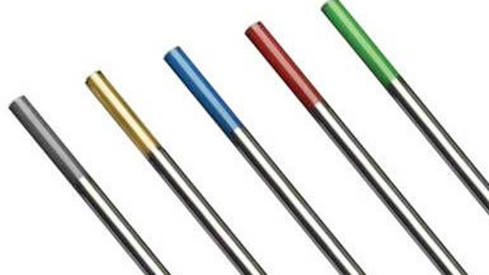
Image by ipotools.eu
Matching Tungsten Alloy to Base Metal and Polarity Requirements
Electrode alloys differ in electron emission, work function, and oxidation resistance. These properties dictate which metals and current types each electrode can handle without excessive wear or arc wander.
Steel, Stainless, and Titanium on DCEN
2% thoriated (red, EWTh-2) and 2% lanthanated (blue, EWLa-2) dominate DCEN work on carbon steel, stainless, chromoly, and titanium. Both deliver reliable arc starts and maintain a sharpened point under sustained current.
Thoriated electrodes carry high amperage with low erosion rates but contain low-level radioactive thorium oxide; grinding dust requires ventilation and collection.
Lanthanated electrodes match or exceed thoriated performance on modern inverters while remaining non-radioactive, making them the preferred replacement in most shops.
Ceriated (gray, EWCe-2) performs well below approximately 90–100 A on thin stainless or instrumentation work where low heat input and easy restarts matter more than high-current capacity.
Aluminum and Magnesium on AC
Traditional pure tungsten (green, EWP) and zirconiated (white or brown, EWZr) form a stable balled tip under AC and resist contamination on older transformer machines.
Pure tungsten balls readily but erodes faster and offers limited current capacity. Zirconiated electrodes handle higher AC amperages with better resistance to splitting and tungsten spitting.
On modern AC/DC inverters with advanced balance and frequency controls, 2% lanthanated or rare-earth blend electrodes (purple) hold a sharpened or truncated point under AC, delivering a more focused arc and longer tip life than pure or zirconiated options.
Many operators now run lanthanated across both AC aluminum and DC steel without changing electrodes between jobs.
All-Purpose and Mixed-Metal Shops
When a single electrode type must cover both AC aluminum and DC steel, 2% lanthanated (blue) or 1.5% lanthanated (gold) provides the widest operating window. These electrodes start easily at low amperage, resist erosion at high current, and maintain arc stability across polarity changes.
Rare-earth multi-oxide blends (often purple) offer similar versatility and are formulated as direct non-radioactive replacements for thoriated electrodes.
Selecting Tungsten Diameter for Amperage Load and Material Thickness
Diameter controls current capacity and arc concentration. Undersized electrodes overheat, ball excessively, and shed tungsten into the weld. Oversized electrodes produce a soft, wandering arc at low amperage and reduce control on thin material.
Practical Current Ranges for Common Diameters
Typical DCEN ranges for alloyed electrodes (thoriated, lanthanated, ceriated) under argon shielding are:
| Diameter | Approximate DCEN Range | Approximate AC Range | Typical Applications |
|---|---|---|---|
| 0.040″ (1.0 mm) | 15–80 A | 10–80 A | Thin sheet, small tubing, precision work |
| 1/16″ (1.6 mm) | 70–150 A | 50–150 A | Light fabrication, exhaust, thin-to-medium sections |
| 3/32″ (2.4 mm) | 150–250 A | 100–250 A | General fabrication, pipe, moderate plate, aluminum |
| 1/8″ (3.2 mm) | 250–400 A | 150–325 A | Heavy plate, high-current production |
| 5/32″ (4.0 mm) | 400–500 A+ | 200–400 A | Very high amperage industrial work |
These ranges vary slightly by alloy and machine waveform. Use the smallest diameter that safely carries the peak current of the joint. For most general shop work spanning 80–200 A, 3/32″ electrodes provide the best balance of capacity and arc focus.
Thickness-Based Starting Points
On mild steel, many operators start near 1 amp per 0.001″ of thickness and refine from there. Thin stainless often runs 10–15% lower current than mild steel of the same thickness to limit heat input.
Aluminum AC settings depend heavily on machine balance and frequency; higher electrode-negative balance increases penetration and allows higher effective amperage before the tip overheats.
Tip Geometry Decisions That Control Arc Shape and Penetration
Tip preparation is inseparable from alloy choice and polarity. The geometry determines arc concentration, cleaning action, and heat distribution into the workpiece.
Pointed and Truncated Tips for DC Work
Grind DC electrodes longitudinally (never circumferentially) to a sharp or truncated point. A sharp point produces a narrow, high-intensity arc suitable for thin material and precise root passes.
Truncating the tip with a small flat (roughly 0.5–1 times electrode diameter) improves arc stability at higher amperages and reduces the risk of the point melting off into the weld.
Included angles between 15° and 45° are common; steeper angles increase penetration and narrow the bead, while shallower angles widen the arc cone.
Ball Formation for Traditional AC
Pure and zirconiated electrodes on older AC machines form a stable hemispherical ball under load. The ball size should not exceed 1.5 times electrode diameter; larger balls cause arc instability and contamination.
Modern lanthanated and rare-earth electrodes on inverter AC often perform better when left pointed or lightly truncated rather than fully balled, because advanced square-wave and balance controls allow a focused arc without the traditional ball.
Grind Quality and Contamination Control
Use a dedicated tungsten grinder or a clean silicon-carbide wheel reserved only for tungsten. Steel or aluminum contamination on the grinding surface transfers to the electrode and produces arc wander or inclusions.
Longitudinal grinding lines parallel to the electrode axis promote smoother electron emission and longer tip life than circumferential marks.
Machine Type and Waveform Effects on Electrode Performance
Inverter machines with adjustable AC balance, frequency, and advanced square-wave output change the performance ranking of electrode types compared with traditional transformer sine-wave machines.
Inverter Advantages for Alloyed Electrodes
Inverters allow higher electrode-negative balance percentages and elevated AC frequencies. These settings increase penetration and arc focus while reducing the heat load on the tungsten.
Lanthanated and ceriated electrodes exploit these controls effectively and often outlast pure or zirconiated electrodes under the same conditions. Operators can maintain a pointed tip on aluminum at moderate amperages, improving control on fillet and outside corner joints.
Transformer Machine Preferences
Older sine-wave machines generate more heat on the electrode during the electrode-positive half-cycle. Pure and zirconiated electrodes handle this thermal cycling by forming a stable ball and resisting cracking. Attempting to run thoriated electrodes on AC with these machines typically causes rapid tip melting and contamination.
Longevity Factors: Storage, Handling, and Reconditioning Limits
Electrode life depends on current density, shielding gas coverage, post-flow time, and mechanical handling more than on alloy alone.
Current Density and Overheating Indicators
Running an electrode near the upper end of its rated range shortens tip life and increases the chance of tungsten inclusions. Visible balling or melting on a DC electrode signals either excessive amperage or insufficient gas coverage.
On AC, excessive electrode-positive time or high amperage produces the same result. Increase diameter or reduce peak current rather than continuing with a deteriorating tip.
Gas Coverage and Post-Flow
Inadequate argon coverage oxidizes the tip between starts and accelerates erosion. Post-flow time should allow the tip to cool below oxidation temperature while still under gas protection; a practical rule is roughly 1 second of post-flow per 0.001″ of electrode diameter, adjusted for torch stick-out and cup size. Contaminated tips (gray, blue, or black oxide layers) must be reground before further use.
Mechanical Damage and Storage
Dropping or bending electrodes introduces stress cracks that lead to premature failure. Store electrodes in clean, dry containers labeled by type and diameter. Avoid mixing alloys in the same container; a single thoriated electrode mixed with lanthanated stock can create identification errors and unnecessary radiation exposure during grinding.
Decision Framework for Daily Shop Selection
Begin with the base metal and polarity. For DC steel or stainless, select lanthanated or thoriated and size the diameter to the upper end of the expected amperage. For AC aluminum on an inverter, start with lanthanated; on a transformer, start with zirconiated or pure.
When the shop runs mixed metals daily, standardize on 2% lanthanated in 1/16″ and 3/32″ diameters and adjust tip geometry rather than changing alloys between jobs.
Record the electrode type, diameter, and tip preparation used on successful procedure qualification records so the selection can be repeated without trial-and-error on production work.
The electrode that delivers consistent arc starts, predictable tip life, and minimal contamination under the specific amperage, polarity, and machine waveform of the joint is the correct choice.
Advanced operators further refine performance by matching included tip angle to joint geometry and by using gas lenses to extend electrode life on high-amperage or restricted-access welds, converting electrode selection from a consumable decision into a controllable process variable.