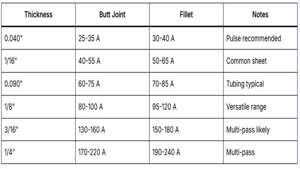
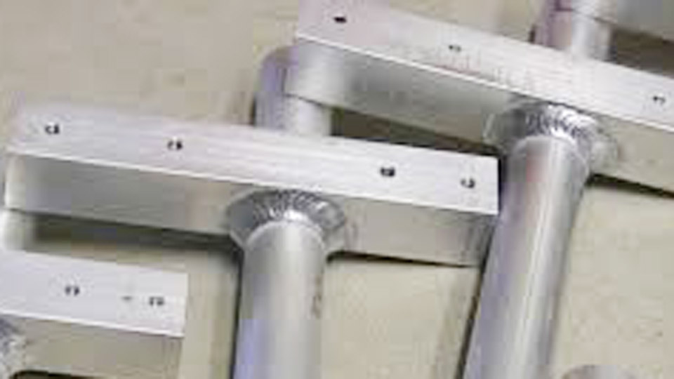
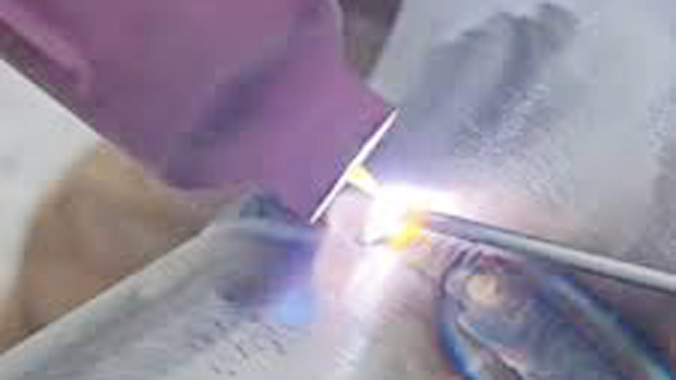
A TIG welding setup chart provides the baseline settings needed to produce consistent, high-quality welds across different metals and thicknesses.
Selecting the correct amperage, tungsten type and size, shielding gas, filler rod, polarity, and cup size is critical because even small setup errors can lead to poor arc stability, inadequate penetration, tungsten contamination, excessive heat input, distortion, or failed weld inspections.
While every welding machine and joint configuration may require fine adjustments, starting with proven settings significantly reduces trial and error, material waste, and rework.
Whether you’re welding mild steel, stainless steel, aluminum, or other alloys, using an accurate TIG welding setup chart helps establish a stable arc and improves overall weld quality.
This guide provides practical reference settings and explains how to adjust them confidently for real-world fabrication and repair applications.
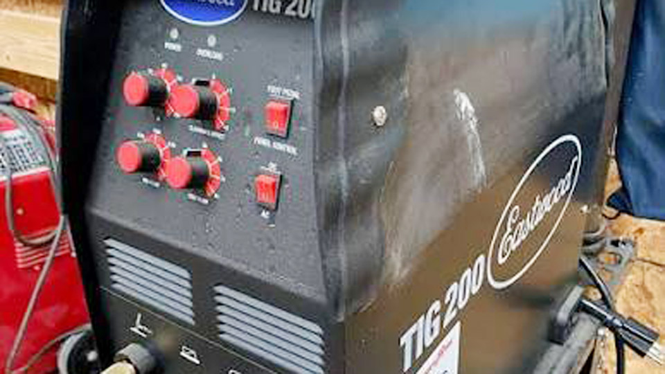
Image by mbauction
Why TIG Welding Setup Matters for Real-World Performance
TIG (GTAW) offers unmatched control and cleanliness, but only when parameters align with material properties, thickness, joint type, and position. A single amp or CFH deviation on thin stock burns through; on thicker sections, it causes incomplete fusion.
Modern inverter machines respond differently than older transformers, and factors like gas lens use, pulse settings, and back-purging further refine outcomes.
Using a targeted TIG welding setup chart eliminates trial-and-error, reduces defects, and improves efficiency across projects from automotive fabrication to pressure vessels.
Core TIG Welding Setup Components
Tungsten Electrode Selection and Preparation
Tungsten choice and geometry dictate arc stability, current capacity, and contamination resistance. Match diameter to amperage range to prevent overheating or arc wander.
Tungsten Diameter and Current Capacity Chart (Approximate Ranges)
| Diameter | DCEN (Steel/SS) | AC (Aluminum) | Typical Use |
|---|---|---|---|
| 1/16″ (1.6mm) | 60–150 A | 45–125 A | Thin materials, precision |
| 3/32″ (2.4mm) | 120–250 A | 80–210 A | General purpose |
| 1/8″ (3.2mm) | 160–330 A | 150–250 A | Medium-thick sections |
| 5/32″ (4.0mm) | 275–480 A | 180–350 A | Heavy plate |
Preparation Guidelines:
- DCEN (steel/stainless): Grind to a 15–30° point with longitudinal marks on a dedicated wheel. Taper length roughly 2–2.5 times diameter for focused arc.
- AC (aluminum): Use zirconiated or lanthanated; allow a slight ball to form naturally. Avoid sharp points on inverters with balanced AC.
- Stick-out: 1/8–1/4″ for standard cups; longer with gas lens for visibility and coverage.
- Preferred types: 2% lanthanated (gold) or ceriated (grey) for versatility across AC/DC and low-amp starts.
Polarity and Current Type Decisions
- DCEN (DC Electrode Negative): Standard for mild steel, stainless, titanium, copper, and nickel alloys. Concentrates ~70% heat into the workpiece for deep, narrow penetration while keeping the tungsten cool.
- AC: Required for aluminum and magnesium. Provides oxide cleaning during the positive half-cycle and penetration on the negative. On inverters, set balance (EN %) to 65–75% for most work—higher EN for penetration on thicker material, lower for cleaning on dirty stock.
- Avoid DCEP in TIG except rare thin-material cases; it overheats the electrode rapidly.
Shielding Gas and Flow Rates
Pure argon (99.995%) handles 90%+ of TIG applications with stable arc and good coverage. Argon/helium mixes (e.g., 75/25) add heat for thick aluminum or copper. Hydrogen or nitrogen blends suit specific stainless or duplex work but require caution.
Gas Flow by Cup Size (Standard Torch, No Drafts)
- #4–#6: 10–15 CFH
- #6–#8: 15–20 CFH
- #8–#10: 20–25 CFH
- Larger/gas lens: 20–30+ CFH
Set pre-flow 0.5–1 sec and post-flow 5–15 sec (roughly 2x electrode diameter in mm) to protect tungsten and puddle during cooling. Use gas lens for extended coverage and reduced flow. Back-purge stainless and titanium roots with argon to prevent oxidation/sugaring.
TIG Welding Setup Charts by Material and Thickness
Mild Steel TIG Setup (DCEN, 100% Argon, ER70S-2 Filler)
Rule of thumb: ~1 amp per 0.001″ of thickness for the thinner piece. Adjust +10–20% for fillets or slower travel; reduce for open roots.
| Thickness | Amps (Butt) | Tungsten | Filler Rod | Cup Size | Gas Flow (CFH) |
|---|---|---|---|---|---|
| 0.035–0.060″ | 30–60 | 1/16″ | 0.040–1/16″ | #4–#6 | 10–15 |
| 0.060–0.125″ | 50–130 | 1/16–3/32″ | 1/16–3/32″ | #5–#8 | 15–20 |
| 1/8″ (0.125″) | 80–130 | 3/32″ | 3/32″ | #6–#8 | 15–20 |
| 3/16″ | 120–180 | 3/32–1/8″ | 1/8″ | #7–#8 | 20–25 |
| 1/4″ | 150–200 | 1/8″ | 1/8″ | #8–#10 | 20–25 |
| 3/8″+ | 200–280+ | 5/32″+ | 3/16″ | #8–#10 | 20–30 |
ER70S-2 offers excellent deoxidizers for clean starts; ER70S-6 tolerates minor surface contamination.
Stainless Steel TIG Setup (DCEN, 100% Argon, ER308L/ER316L Filler)
Stainless runs cooler (~0.8 amp per 0.001″). Prioritize low heat input, faster travel, and back-purging to maintain corrosion resistance and avoid sensitization.
| Thickness | Amps | Tungsten | Filler | Cup/Gas |
|---|---|---|---|---|
| 0.035–0.060″ | 25–50 | 1/16″ | 0.040–1/16″ | #4–#6 / 10–15 CFH |
| 0.060–0.125″ | 40–100 | 1/16–3/32″ | 1/16–3/32″ | #5–#8 / 15–20 |
| 1/8″ | 70–120 | 3/32″ | 3/32″ | #6–#8 / 15–20 |
| 3/16″ | 100–160 | 3/32–1/8″ | 3/32–1/8″ | #7–#8 / 20–25 |
| 1/4″ | 130–190 | 1/8″ | 1/8″ | #8–#10 / 20–25 |
Use pulse (e.g., 1–2 Hz, 30–50% background) on thin stainless to control heat and distortion.
Aluminum TIG Setup (AC, 100% Argon, ER4043 or ER5356 Filler)
Aluminum demands ~1.2 amps per 0.001″ plus AC adjustments. ER4043 flows better for general work; ER5356 provides higher strength. Clean oxide thoroughly (stainless brush, solvent) immediately before welding.
| Thickness | AC Amps | Tungsten | Filler | Cup/Gas | AC Balance (EN%) |
|---|---|---|---|---|---|
| 0.035–0.060″ | 30–70 | 1/16″ | 1/16″ | #5–#7 / 15–20 | 60–65 |
| 1/16–1/8″ | 60–140 | 3/32–1/8″ | 3/32–1/8″ | #6–#8 / 15–25 | 65–70 |
| 3/16″ | 120–180 | 1/8–5/32″ | 1/8–5/32″ | #7–#10 / 20–30 | 70 |
| 1/4″ | 160–240 | 5/32″ | 3/16″ | #8–#10 / 25–30 | 70–75 |
Higher frequency (100–150 Hz) narrows the arc for precision; helium mixes help on thicker sections.
Advanced TIG Parameters and Techniques
Pulse TIG for Control
Pulse reduces average heat input while maintaining penetration. Typical: 1–2 Hz for steel (higher on thin), 40–60 PPS on stainless for tight control. Background current 20–50% of peak. Ideal for thin-to-thick transitions and positional work.
Torch Technique and Arc Length
Maintain 1/16–1/8″ arc length. Push at 10–20° travel angle. Add filler rod to the leading edge of the puddle at consistent rhythm—too slow overheats, too fast causes lack of fusion. Use foot pedal for real-time amperage modulation on variable thickness or starts/stops.
Joint and Position Adjustments
- Butt joints on thin material: Lower amps, faster travel.
- Fillets: Slightly higher amps for sidewall fusion.
- Vertical/uphill: Reduce amps 10–15%, smaller puddle.
- Overhead: Tight parameters and pulse to manage gravity.
Multi-pass on thick material: Maintain interpass temps (e.g., <150°C for stainless) and clean between passes.
Filler Rod and Consumable Matching
Select filler to match or overmatch base metal chemistry and strength. Diameter typically matches or is one size smaller than tungsten. Common choices:
- Mild steel: ER70S-2 (clean) or ER70S-6.
- Stainless: ER308L/316L (low carbon “L” for corrosion).
- Aluminum: ER4043 (weldability) or ER5356 (strength).
Machine Setup and Troubleshooting Common Issues
Connect torch (negative for DCEN), ground clamp securely, and verify gas flow. Use HF start for clean ignition. Test settings on scrap matching your job.
Watch for:
- Tungsten contamination: Regrind immediately; indicates touch or poor gas.
- Porosity: Drafts, low flow, dirty metal, or insufficient post-flow.
- Lack of fusion: Increase amps or slow travel.
- Sugaring on stainless: Back-purge and use trailing shield if needed.
Real-World Application Insights
Effective TIG welding setup charts translate directly to better joints in pipe, sheet, automotive, and art fabrication. Professionals dial parameters for code compliance and repeatability; hobbyists gain confidence for visible, high-quality work.
Always verify with test coupons under actual conditions—material heat sink, joint fit-up, and machine characteristics vary.
Mastering these decisions—balancing heat input, shielding, and filler addition—elevates TIG from frustrating to precise and repeatable. The next level involves integrating pulse waveforms and advanced AC balance for exotic alloys or high-productivity orbital work, where parameter precision defines success.
FAQ
What is the best starting amperage for 1/8″ mild steel TIG welding?
For 1/8″ mild steel butt joint, start at 90–130 amps DCEN with 3/32″ tungsten and 15–20 CFH argon. Fine-tune with foot pedal based on puddle behavior and travel speed.
How does TIG setup differ for stainless steel vs mild steel?
Stainless requires 10–20% lower amperage, stricter heat control, back-purging, and often pulse to prevent distortion and maintain corrosion resistance. Use matching low-carbon filler like ER308L.
What gas flow rate and cup size for aluminum TIG?
Use 15–25 CFH with #6–#8 cups for most aluminum thicknesses. Increase for larger cups or drafts; argon/helium helps thicker sections. Ensure adequate post-flow.
Which tungsten works best for both AC and DC TIG?
2% lanthanated (gold) or ceriated (grey) electrodes offer excellent versatility, arc starts, and capacity for both AC aluminum and DCEN ferrous metals on inverter machines.