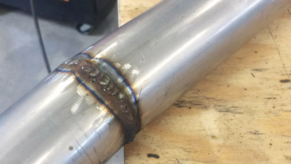
Porosity shows up as tiny holes or a spongy surface on the bead even when voltage, wire speed, and travel look correct. In most cases the root cause is incorrect shielding-gas delivery.
The phrase ideal gas pressure for MIG welding is widely searched, yet the number that actually protects the weld pool is flow rate measured in cubic feet per hour (CFH), not the high-pressure reading on the cylinder gauge.
Setting the wrong flow wastes expensive gas, creates turbulence that sucks air into the arc, or leaves the molten metal exposed to oxygen and nitrogen. Getting the flow right eliminates those defects, stabilizes the arc, and extends cylinder life without changing any other machine parameter.
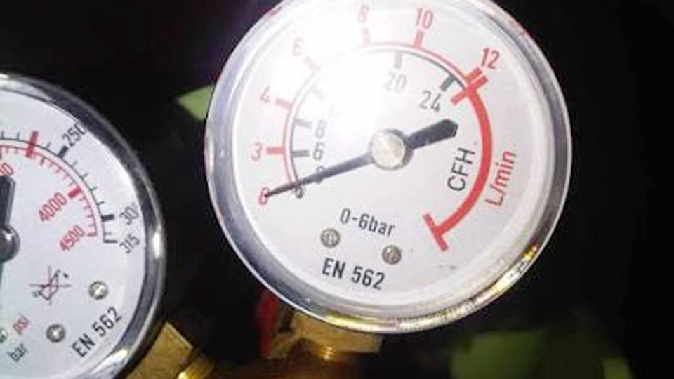
Image by mig-welding.co.uk
Pressure Versus Flow Rate on the Regulator
Cylinder pressure and delivery flow are two different values controlled by different parts of the regulator.
Cylinder Gauge Versus Delivery Flowmeter
A full argon or argon-CO₂ cylinder typically reads 2,000–2,400 psi. Pure CO₂ cylinders sit at 500–750 psi while liquid remains. These numbers only tell remaining content; they do not control the shield at the nozzle.
The second gauge or the ball in the flow tube shows the actual CFH leaving the regulator while gas is flowing. Always set and verify flow with the gun trigger depressed so the reading reflects real delivery, not static pressure.
Typical Regulator Delivery Pressures
Most flowmeter-style regulators operate with an internal working pressure of 20–50 psi upstream of the needle valve. Flow-gauge regulators (single adjustable orifice) are commonly set in the 25–40 psi range to achieve the desired CFH. Neither of these numbers is the “gas pressure” that protects the weld; the CFH value is.
Recommended Flow Rates by Material and Gas Mix
Flow requirements change with base metal reactivity, transfer mode, and gas density.
Mild Steel with C25 or Pure CO₂
Indoor short-circuit transfer on clean steel starts cleanly at 15–25 CFH. Still-air shops can often run 10–15 CFH without porosity. When any draft is present or the bead shows pinholes, raise flow to 20–30 CFH. Spray-transfer modes on thicker plate usually sit at the upper end of that band because the weld pool is larger and hotter.
Aluminum with 100 % Argon
Aluminum oxidizes rapidly, so coverage must be denser. Indoor work typically needs 25–35 CFH. Helium-argon blends for thick sections push the requirement higher—often 35–50 CFH—because helium disperses more readily.
Stainless Steel with Tri-Mix or High-Argon Blends
Short-circuit and pulsed modes run well at 20–30 CFH. Tri-mix gases containing helium need the higher side of the range to maintain adequate density around the arc.
How Nozzle Diameter Changes Required Flow
Gas must fill the nozzle volume and exit in laminar flow. Larger nozzles demand higher CFH to achieve the same exit velocity and coverage envelope.
Standard Nozzle Ranges
- ⅜-inch nozzle: 15–22 CFH typical, maximum around 30 CFH before turbulence
- ½-inch nozzle: 20–30 CFH typical, maximum near 40 CFH
- ⅝-inch nozzle: 25–35 CFH typical
- ¾-inch and larger: 30–40 CFH starting point
Exceeding the maximum for a given nozzle creates a Venturi effect that pulls atmospheric air into the shield, producing the same porosity that low flow causes.
Stick-Out and Cup-to-Work Distance
Longer contact-tip-to-work distances and wider joint openings increase the volume that must be protected. Raise flow 3–5 CFH when stick-out exceeds ¾ inch or when welding deep grooves.
Indoor, Drafty, and Outdoor Conditions
Air movement is the single largest external variable affecting shield integrity.
Still Indoor Air
10–20 CFH is often sufficient for mild steel once the setup is leak-free. Most production shops standardize on 20–25 CFH for consistency across operators and shifts.
Light Draft or Open Shop Doors
Increase 5–10 CFH or add temporary barriers. Fans directed near the work must be blocked or redirected; even low-velocity air strips the gas envelope.
Outdoor or Windy Work
MIG shielding is marginal above 5 mph without protection. Raise flow to 30–40 CFH and use wind screens or tents. Beyond that point flux-cored wire with self-shielding capability becomes more practical than fighting gas loss.
Setting and Verifying the Flow Correctly
Trigger-Pulled Calibration
Open the cylinder valve fully, then open the regulator. Depress the gun trigger and adjust the flowmeter ball or flow-gauge needle to the target CFH while gas is actually flowing. Static readings taken with the trigger released are inaccurate because residual pressure in the hose inflates the number.
Leak Checks Before Welding
Soap-test every fitting from cylinder to gun. A small leak at a hose barb or diffuser can drop effective flow by 5–10 CFH without any change on the regulator dial. Clean the nozzle and diffuser regularly; spatter buildup restricts exit area and forces operators to raise the set point unnecessarily.
Reading Weld Results to Fine-Tune Flow
Signs of Insufficient Flow
Scattered porosity, gray or black surface oxidation, and an unstable arc that “hunts.” The bead may look otherwise normal until sectioned or bend-tested.
Signs of Excessive Flow
Porosity concentrated at the start of the bead, excessive spatter, and a hissing sound louder than normal. The gas itself becomes turbulent and entrains air. Reducing flow 5 CFH often eliminates the defect immediately.
Transfer-Mode Adjustments
Short-circuit transfer tolerates the lower end of each range. Globular and spray transfer enlarge the molten pool and usually need 5–10 CFH more coverage for the same nozzle.
Gas Consumption and Cylinder Runtime Considerations
At 20 CFH a standard 125-cubic-foot cylinder yields roughly six hours of continuous arc time. Raising the set point to 35 CFH cuts runtime by nearly half and increases cost without improving quality once adequate coverage is achieved. Tracking actual arc-on time versus cylinder change-outs quickly reveals whether the flow setting is optimized or wasteful.
Wrapping Up
Choosing the correct delivery flow for any given MIG setup is a balance of nozzle size, metal type, transfer mode, and ambient air movement. Start with the mid-range value for the material and nozzle, verify with the trigger pulled, then adjust only far enough to eliminate porosity or turbulence.
Once that stable window is found, record the CFH, gas mix, and nozzle size so every subsequent operator can reproduce the same shield without trial-and-error.
Advanced operators further reduce gas waste by fitting surge-limiting orifices or gas-saver systems that eliminate the high-pressure blast that occurs at every trigger pull, cutting overall consumption 20–40 % while keeping the steady-state flow exactly where the weld requires it.
FAQs
What is the ideal gas pressure for MIG welding mild steel?
For indoor mild steel with C25 or CO₂, set flow to 15–25 CFH. Start at 20 CFH and adjust only if porosity appears.
How many CFH for MIG welding aluminum?
Use 25–35 CFH of 100 % argon indoors. Raise toward 40 CFH if the joint is large or any draft is present.
What happens if MIG gas flow is too high?
Flow above roughly 35–40 CFH on a standard nozzle creates turbulence that pulls air into the shield, causing porosity and wasting gas.
Should I set MIG gas by PSI or CFH?
Always set and verify by CFH on the flowmeter while the trigger is depressed. Cylinder PSI only indicates remaining gas volume.