
Accurately determining how to calculate welding time is essential for estimating project costs, scheduling production, and improving overall shop efficiency. Welding time is more than the arc-on period—it depends on weld length, travel speed, joint design, welding process, material thickness, and setup requirements.
Miscalculating these factors can lead to inaccurate quotes, missed deadlines, labor overruns, and reduced productivity on the shop floor.
Whether you’re preparing a fabrication estimate, planning a construction project, or optimizing manufacturing operations, understanding the correct calculation method helps you make informed decisions based on realistic production rates.
By applying the right formulas and accounting for practical welding variables, you can produce more accurate time estimates, improve workflow planning, and better manage both labor and project costs.
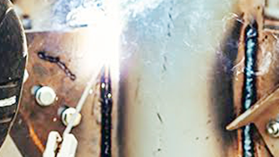
Image by red-d-arc
Fundamentals of Welding Time Calculation
Welding time breaks into two primary components that must be distinguished for realistic planning.
Arc Time vs. Total Labor Time
Arc time represents the pure duration the welding arc burns and deposits metal. It equals total weld length divided by travel speed, or weld metal weight divided by deposition rate (at 100% efficiency).
Total labor time includes arc time plus all non-arc activities: setup, joint preparation, interpass cleaning, electrode or wire changes, grinding, repositioning, inspection, and breaks.
The gap between these is captured by the operator factor (also called arc-on factor or duty cycle in this context), typically 20-40% for manual welding in shop environments and lower in field conditions.
Key Variables Influencing Calculation Accuracy
- Weld metal volume/weight: Determined by joint geometry.
- Deposition rate: Pounds or kilograms of weld metal deposited per hour.
- Travel speed: Inches or millimeters per minute along the joint.
- Operator factor: Percentage of time spent actually welding.
- Process-specific factors: Number of passes, position, preheat requirements, and post-weld activities.
Ignoring any variable leads to significant errors, especially on multi-pass or out-of-position welds.
Calculating Weld Metal Volume and Weight
Precise volume calculation forms the foundation of time estimation. Overestimating filler leads to excess cost; underestimating extends time.
Fillet Weld Volume Formulas
For a standard fillet weld, cross-sectional area approximates as a right triangle: Area (in²) = (leg size²) / 2. For a 1/4-inch leg fillet, area ≈ 0.03125 in². Multiply by weld length in inches for volume, then by material density (0.283 lb/in³ for steel) for weight.
Adjust for reinforcement (typically 1/16 to 1/8 inch) and actual throat measurement. Convex fillets increase volume by 10-20% compared to flat.
Groove Weld (Butt Joint) Calculations
Single-V groove volume includes:
- Root gap area: gap × thickness
- Bevel areas: 2 × (thickness × tan(bevel angle) × thickness / 2)
- Reinforcement cap: approximated as (cap width × height) / 2
For a 60° included angle single-V on 1/2-inch plate with 1/16-inch root gap and 1/8-inch reinforcement, total cross-section area can exceed 0.3-0.4 in² per linear inch. Double-V grooves roughly double this for thicker material but reduce per-side volume.
Use density conversions: steel ~7.85 g/cm³ or 0.283 lb/in³. Stainless is slightly lower at ~0.29 lb/in³ in some alloys.
Material Density and Alloy Adjustments
Always confirm alloy density. Aluminum (0.098 lb/in³) requires roughly 1/3 the weight of steel for the same volume, dramatically reducing arc time but often needing more passes due to lower heat input tolerance. High-nickel alloys demand careful calculation due to higher densities and slower deposition characteristics.
Deposition Rates Across Common Welding Processes
Deposition rate directly scales arc time. Published rates assume optimal parameters and 100% arc-on time.
| Process | Typical Deposition Rate (lb/hr) | Efficiency (%) | Best Applications |
|---|---|---|---|
| SMAW (Stick, E7018 1/8″) | 2.5–5.5 | 58–68 | Field repairs, all positions |
| GMAW (MIG, 0.035″ solid, spray) | 8–15 | 85–98 | Shop fabrication, thicker plate |
| FCAW (Gas-shielded) | 10–28 | 80–88 | Structural, heavy plate |
| GTAW (TIG, manual) | 1.5–4 | 95–99 | Precision, thin materials, code work |
FCAW often achieves highest manual rates on long seams, while TIG prioritizes quality over speed. Deposition rises with wire diameter and current but is limited by position and heat input requirements.
Process-Specific Deposition Insights
SMAW rates drop significantly due to stub loss and slag removal. MIG in short-circuit mode on thin material stays in the 3-6 lb/hr range, while spray transfer on thicker sections pushes higher. Flux-cored wires excel in out-of-position work when parameters balance slag fluidity and travel speed.
Travel Speed and Its Impact on Welding Time
Travel speed often provides the most direct arc time calculation for linear welds: Arc Time (minutes) = (Weld Length in inches) / Travel Speed (IPM).
Typical Travel Speeds
- MIG spray transfer on 1/4–1/2″ plate: 10–20 IPM
- FCAW structural fillets: 8–18 IPM
- TIG root passes: 2–6 IPM
- Stick vertical-up: 4–8 IPM
Experienced operators achieve higher consistent speeds with proper parameters. Too fast risks lack of fusion; too slow causes excessive heat input, distortion, and reduced productivity.
Position dramatically affects speed: flat and horizontal allow maximum rates, while overhead or vertical-up can halve them due to puddle control needs.
Operator Factor and Real-World Efficiency
No welder maintains 100% arc time. Industry averages hover around 20-30% for manual processes in typical shops.
Standard Operator Factors
- High-volume shop MIG/FCAW: 30–45%
- Field stick or TIG: 15–25%
- Precision code work: 10–20%
Total Labor Time = Arc Time / Operator Factor.
A 30% operator factor means total time is roughly 3.3× arc time.
Strategies to Improve Operator Factor
Optimize fixturing for quick repositioning, use wire feeders with long reach to minimize stops, pre-clean joints thoroughly, and sequence welds to reduce interpass cooling waits. Robotic or mechanized setups push operator factors above 70-80%.
Comprehensive Formula for Total Welding Time
- Calculate total weld metal weight (W) in lbs.
- Determine deposition rate (DR) in lbs/hr for chosen process/parameters.
- Arc Time (hours) = W / DR
- Apply operator factor (OF as decimal): Total Labor Time (hours) = Arc Time / OF
- Add setup, fit-up, and post-weld time separately for full project estimate.
For travel speed method: Arc Time (min) = Total Length (in) / Speed (IPM). Convert and adjust with operator factor.
Practical Examples Across Processes
MIG Welding Structural Fillets
Consider 50 linear feet of 1/4″ fillet welds on A36 steel using 0.035″ wire at 12 lb/hr deposition and 15 IPM travel speed. Weld weight ≈ 50 ft × 12 in × 0.03125 in² × 0.283 lb/in³ ≈ 5.3 lbs. Arc time ≈ 5.3 / 12 ≈ 0.44 hours (26 min). At 35% operator factor, total labor ≈ 1.26 hours. Add fit-up and cleanup for realistic bid.
TIG on Thin Stainless Pipe
For 10 feet of 1/8″ wall stainless butt welds, lower deposition (2.5 lb/hr) and slower travel (4 IPM) yield longer arc times. Multiple passes increase volume. Expect significantly higher total labor multiplier due to precision cleaning and lower operator factor.
These examples highlight why process selection dramatically alters timelines.
Advanced Considerations for Multi-Pass and Complex Joints
Thicker materials require multiple passes, each with its own setup time. Calculate per-pass volume and sum. Vertical and overhead positions demand slower speeds and more frequent stops.
Preheat and interpass temperature control add non-arc time, especially on alloy steels. Distortion management through sequencing or clamping further impacts total duration.
Joint preparation quality directly affects time—poor fit-up forces slower travel or additional passes to bridge gaps.
Tools and Modern Methods for Estimation
Manual calculations work for small jobs, but spreadsheets or dedicated software (such as ESAB’s Quick Weld Productivity Analyzer) incorporate joint libraries, material databases, and efficiency factors for rapid iteration.
Digital tools allow sensitivity analysis: test how changing from stick to FCAW impacts total project time. Track actual vs. estimated times on completed jobs to refine your personal operator factors and deposition assumptions.
Decision-Making for Welding Projects
Mastering how to calculate welding time equips you to select optimal processes, set competitive yet profitable bids, and schedule resources effectively. Prioritize detailed joint analysis and verified deposition data over rough guesses, especially on larger or repeat jobs.
A pro-level insight: the highest performers treat welding time as a system optimization problem—balancing deposition rate, travel consistency, and operator factor through continuous parameter tuning and workflow refinement rather than simply pushing higher amperage. This holistic approach consistently delivers both quality and productivity gains that compound across projects.
FAQ
How does weld position affect calculated welding time?
Vertical and overhead positions typically reduce travel speed by 30-50% and lower operator factor due to fatigue and puddle control, increasing total time significantly compared to flat welding.
What is a realistic operator factor for hobbyist vs. professional welders?
Hobbyists often fall below 20% due to frequent interruptions and setup. Professionals in optimized shops achieve 30-45% with MIG/FCAW through better workflow and tooling.
Can I use travel speed alone for quick estimates?
Yes, for simple linear welds it provides fast arc time: length divided by IPM. Always multiply by your verified operator factor and add non-welding activities for total labor.
How do material thickness and joint type change time calculations?
Thicker sections require more passes and higher total weld metal volume, multiplying arc time. Groove joints demand precise bevel calculations, while fillets are simpler but sensitive to leg size variations.


