Push-to-connect fittings have become a common solution in plumbing, compressed air, and fluid transfer systems because they simplify installation without soldering, threading, or welding.
Understanding How Does Push to Connect Fittings Work is important for fabricators, maintenance technicians, and welders who frequently integrate piping systems into larger projects.
A fitting that is installed incorrectly or used in the wrong application can lead to leaks, pressure loss, system downtime, and costly rework.
These fittings rely on an internal gripping mechanism and sealing components that create a secure connection when tubing is inserted to the proper depth.
Their speed and ease of use make them attractive for repairs and new installations, but performance depends on proper material compatibility, pressure ratings, and installation practices.
Knowing how the connection is formed and maintained helps ensure reliable system performance while reducing installation time and potential failures in the field.
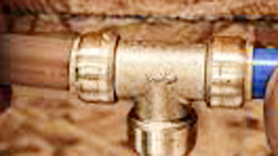
Image by plumbermag
The Mechanics Behind Push to Connect Fittings
Internal Components and Locking Action
Push to connect fittings rely on a collet with stainless steel teeth or gripping ring, paired with one or more O-rings (typically EPDM or similar elastomers) for sealing.
When you insert properly prepared tubing, the collet expands slightly then snaps back, driving the teeth into the tube’s outer surface. The O-ring compresses around the tube, creating a leak-proof seal that holds under pressure.
The design allows rotation after connection in many models, useful when routing hoses around weld tables or machines without twisting lines. Release involves depressing the collet or release collar, which retracts the teeth and lets you pull the tube free—often without damaging the tubing for reuse if cut cleanly.
Pressure and Flow Dynamics
These fittings handle typical welding pressures well: shop air systems often run 90–120 psi, while shielding gas (argon, CO2 mixes) operates at 20–50 psi regulator output. Quality brass or stainless versions rate 150–300 psi or higher depending on size and manufacturer, with some pneumatic models exceeding 200 psi safely.
Flow restriction remains minimal because the internal bore closely matches common tubing IDs (e.g., 1/4″ or 3/8″ tube).
In practice, a sudden pressure surge from a compressor kick-in or cylinder valve opening tests the grip. The teeth distribute force evenly, preventing tube slippage better than many older barb fittings under vibration from welders or grinders.
Materials and Compatibility for Welding Environments
Tubing Choices: Polyurethane, Nylon, or Copper
Welders commonly use polyurethane tubing for flexibility and abrasion resistance in shop air drops, or nylon for better kink resistance in gas lines.
For shielding gas delivery to MIG or TIG machines, semi-rigid polyethylene or specific inert-gas-rated hose works with push fittings sized for 1/4″ or 5/16″ OD. Avoid mixing incompatible materials—polyurethane pairs best with fittings designed for its durometer.
Brass bodies with nickel plating resist corrosion from shop humidity and weld spatter exposure. Stainless steel versions excel for high-purity argon lines or outdoor setups where moisture could pit brass over time. Plastic-bodied fittings suffice for low-pressure secondary lines but lack the durability for primary shop manifolds.
Temperature Considerations in the Shop
Welding bays see heat from arcs, preheat torches, and summer conditions. Most push fittings handle 0–150°F (–18–65°C) continuously; check specs for spikes near 200°F. O-ring materials degrade faster above rated temps, leading to slow leaks that contaminate shielding gas and cause porosity.
For hot zones near plasma cutters or heavy preheat, consider compression or threaded alternatives with high-temp seals.
Installing Push to Connect Fittings in Your Welding Setup
Preparation Steps for Leak-Free Joints
Cut tubing square with a sharp tube cutter or dedicated plastic pipe shears—never a hacksaw, which leaves burrs and uneven ends. Deburr inside and outside thoroughly; even small ridges prevent the O-ring from seating fully.
Mark insertion depth on the tube (usually 1–1.5 inches depending on size) to ensure full engagement past the O-ring and into the gripping zone. Clean the tube end of oils, metal filings, or weld dust.
Push firmly until you feel the tube bottom out and the collet engage. Tug gently to confirm lock. For air lines feeding plasma cutters or grinders, pressure-test at 1.5x operating pressure. For shielding gas, flow-test with a meter at the torch to verify no restriction or leaks.
Common Configurations in Welding Shops
- Shop Air Manifolds: Run 3/8″ or 1/2″ poly tubing from compressor to multiple drops with push tees and elbows for quick tool swaps.
- Shielding Gas Distribution: Use smaller 1/4″ lines from a central regulator or manifold to individual machines. Push fittings allow easy reconfiguration when adding a new TIG station.
- Coolant Lines on Water-Cooled Torches: Low-pressure push fittings simplify routing without introducing air pockets if installed with proper slope and purging.
Comparing Push to Connect vs. Traditional Welding Shop Connections
Versus Compression Fittings
Compression fittings use a ferrule that deforms around the tube under nut torque, offering excellent vibration resistance for permanent installs. Push to connect versions install faster—no wrenches needed in tight spaces behind machines—but may require more careful tube prep.
Compression edges out in very high-pressure or high-vibration direct-on-machine applications; push wins for frequent reconfiguration.
Versus Threaded and Barbed Fittings
Threaded joints demand Teflon tape or sealant and risk cross-threading on soft tubing adapters. Barbed fittings with hose clamps work but create more flow turbulence and leak risk under repeated flexing. Push to connect reduces assembly time dramatically while maintaining cleaner internal flow paths critical for consistent gas delivery to the weld pool.
When to Choose Push to Connect
Opt for them in dynamic shop environments where you frequently move machines, extend runs, or need to isolate sections for maintenance. They shine for hobbyists and small shops lacking extensive pipefitting tools.
For fixed, high-volume industrial manifolds carrying high-pressure air (>150 psi continuous), hybrid systems or welded pipe may prove more economical long-term.
Sizing, Pressure Ratings, and Flow Calculations for Welders
Select fittings by matching tube OD precisely—common welding sizes include 1/4″, 5/16″, 3/8″, and 1/2″. Flow capacity scales with internal diameter: a 1/4″ OD tube with ~0.16–0.20″ ID supports adequate shielding gas for most MIG/TIG work (15–40 CFH). Larger 3/8″ suits main shop air feeds to multiple tools.
Calculate approximate pressure drop using tubing length, ID, and flow rate. For a 50-ft 1/4″ line at 30 CFH argon, drop stays negligible (<2 psi). Exceeding recommended lengths or using undersized tubing causes inconsistent flow, leading to poor shielding and defects like oxidation or lack of fusion.
Use this quick reference for typical applications:
| Application | Recommended Tube OD | Typical Pressure | Key Consideration |
|---|---|---|---|
| Shielding Gas to MIG/TIG | 1/4″ | 20–50 psi | Low turbulence, clean interior |
| Shop Air Drops | 3/8″–1/2″ | 90–120 psi | Abrasion resistance |
| Plasma Cutter Air | 3/8″ | 80–110 psi | High flow volume |
| Coolant Lines | 1/4″–5/16″ | <30 psi | Chemical compatibility with coolant |
Troubleshooting and Maintenance in Real Welding Conditions
Diagnosing Leaks
Listen for hissing or use soapy water solution at joints under pressure. Common causes: incomplete insertion, damaged O-rings from sharp tube ends, or tubing that is out-of-round. Re-cut and re-insert; if persistent, replace the fitting. Contaminants in shielding gas lines amplify issues—flush new setups with dry gas before welding.
Long-Term Performance Factors
Vibration from compressors and frequent hose movement eventually fatigues grips. Inspect quarterly in high-use shops. Replace O-rings proactively (many fittings allow it).
Avoid over-flexing tubing right at the fitting exit; use strain relief or supports. For gas purity, dedicate separate lines and fittings for argon vs. CO2 mixes to prevent cross-contamination.
In cold shops, tubing stiffens—warm it slightly before insertion for better seal. Heat near welds can soften plastic bodies; position fittings away from direct arc heat or spatter zones.
Advanced Applications and Custom Shop Setups
Many welders build modular manifolds using push tees, manifolds, and shut-off valves for multi-machine bays. Combine with quick-disconnect couplers for torch gas lines to enable rapid swaps between processes.
For mobile rigs or field work, push fittings on coiled polyurethane hose create lightweight, tangle-resistant extensions.
Pro-level insight: Integrate flowmeters downstream of push connections on critical TIG setups. Even minor leaks or restrictions invisible at the regulator show up as unstable gas coverage at the torch, directly impacting puddle control and mechanical properties. Monitoring here separates good welds from excellent ones.
Real-World Application Insight
Push to connect fittings excel when your workflow demands speed and flexibility without sacrificing reliability in air and low-pressure gas systems. Match materials, prep tubing meticulously, and pressure-test setups to match your specific welding pressures and environments.
This approach minimizes downtime, ensures consistent shielding, and lets you focus on the arc rather than chasing leaks. For high-purity or extreme-duty applications, layer them strategically with traditional methods where permanent strength matters most.