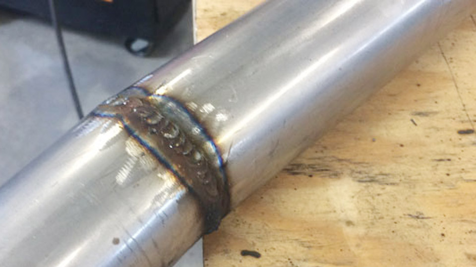
Selecting the Best MIG Welding Settings is one of the most important factors in producing strong, consistent welds. Even with quality equipment and proper technique, incorrect voltage, wire feed speed, or shielding gas settings can cause poor penetration, excessive spatter, lack of fusion, burn-through, and unstable arc performance.
The right setup depends on material thickness, metal type, wire diameter, and welding position, making a single setting unsuitable for every job.
Understanding how these variables work together improves weld quality, reduces rework, minimizes material waste, and helps meet fabrication or inspection requirements.
Whether you’re welding mild steel, stainless steel, or aluminum, knowing how to adjust your machine for the application leads to more reliable results and greater confidence in every weld.
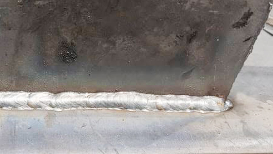
Image by r/Welding
Understanding Core MIG Parameters
Voltage: Arc Length and Bead Profile Control
Voltage primarily controls arc length and influences bead width and height. Higher voltage produces a longer arc, flatter and wider beads, and more heat. Lower voltage yields a shorter arc, narrower and more convex beads with less heat input.
For most mild steel work:
- Thin materials (1-2 mm): 15-17 V
- 3 mm (1/8″): 17-18 V
- 5-6 mm (3/16″ to 1/4″): 18-21 V
Adjust in 0.5 V increments. Too high voltage causes undercut or spatter; too low leads to unstable arc and poor fusion. Voltage interacts closely with WFS—imbalance is the most common source of poor performance.
Wire Feed Speed (WFS) and Amperage Relationship
WFS determines deposition rate and directly affects amperage (higher WFS = higher amps). A rough guide is ~1 amp per 0.001″ of mild steel thickness. Stainless requires 10-15% less current; aluminum needs ~25% more due to conductivity.
Typical starting ranges (0.030″ wire, mild steel):
- 2 mm: 120-150 IPM
- 3 mm: 150-180 IPM
- 6 mm: 220-260 IPM
Match WFS to voltage. Excessive WFS for the voltage causes stubbing and spatter. Insufficient WFS burns the wire back into the contact tip.
Shielding Gas Type and Flow Rate
Shielding gas protects the weld pool. Common mixes:
- Mild steel: 75% Ar / 25% CO2 (C25) — good balance of arc stability and penetration.
- Stainless: 98% Ar / 2% CO2 or tri-mix (90% He / 7.5% Ar / 2.5% CO2).
- Aluminum: 100% Argon.
Flow rates: 15-25 CFH indoors for most work. Start at 20 CFH and adjust for drafts or nozzle size. Too low causes porosity; too high creates turbulence and pulls in air.
MIG Settings by Material Thickness for Mild Steel
Thin Gauge and Sheet Metal (Up to 3 mm)
Focus on short-circuit transfer to minimize heat input and distortion. Use 0.023″ or 0.030″ wire.
Example settings (0.023″ wire, C25 gas):
- 1 mm: 15-16 V, 90-120 IPM, 15-20 CFH
- 2 mm: 16-17 V, 120-150 IPM, 15-20 CFH
- 3 mm: 17-18 V, 150-180 IPM, 18-22 CFH
Maintain short stickout (3/8″–1/2″). Push technique helps with gas coverage. Test on scrap to avoid burn-through—travel speed is critical here.
Medium Thickness (3-6 mm)
Transition to balanced parameters supporting globular or early spray transfer where appropriate. 0.030″ or 0.035″ wire is ideal.
- 1/8″ (3 mm): 17-19 V, 150-220 IPM
- 3/16″ (5 mm): 18-20 V, 180-250 IPM
- 1/4″ (6 mm): 19-21 V, 220-300 IPM (adjust for joint type)
These ranges support good penetration without excessive heat. For fillet welds, slightly higher WFS improves wash-in on the toes.
Thicker Sections (Over 6 mm)
Higher parameters and possibly larger wire (0.035″-0.045″). Multiple passes become necessary. Bevel edges for better fusion on heavy plate.
Typical: 21-25+ V and 300+ IPM depending on exact thickness and position. Monitor interpass temperature to control distortion.
Best Settings for Stainless Steel and Aluminum
Stainless Steel MIG Parameters
Stainless demands lower overall heat to preserve corrosion resistance and minimize distortion. Use ER308L or similar wire.
Starting points:
- Thin (1-2 mm): 15-17 V, 90-140 IPM, tri-mix or 98/2 gas
- 3-4 mm: 17-20 V, 150-250 IPM
Faster travel speeds prevent overheating. Back-purge when possible for high-purity applications. Expect tighter parameters than mild steel—test thoroughly.
Aluminum MIG Settings
Aluminum’s high thermal conductivity requires higher energy input and pure argon. Spool gun recommended for consistent feeding.
- 2 mm: 17-19 V, 200-300 IPM
- 3-4 mm: 19-22 V, 250-400 IPM
Push technique is essential. Clean oxide layer immediately before welding. Higher WFS compensates for rapid heat dissipation.
MIG Transfer Modes and When to Use Them
Short-Circuit Transfer
Low voltage/WFS (typically 16-22 V range). Wire contacts the pool 90-200 times per second. Excellent for thin materials, all positions, and root passes. Lower heat input reduces distortion.
Ideal for sheet metal and positional work. More spatter possible but controllable with proper settings.
Globular Transfer
Transition mode with larger droplets. Moderate parameters. Less common today due to spatter but useful in some applications with CO2-rich gas.
Spray Transfer
Higher voltage (22-30+ V) and WFS with high argon mixes (80%+ Ar). Smooth, stable arc with fine droplets. High deposition, excellent for thicker materials in flat/horizontal positions. Minimal spatter.
Requires sufficient power source output. Not suitable for thin stock.
Pulsed Spray
Advanced mode available on modern machines. Alternates high/low current for best of both worlds: low average heat with spray-like deposition. Superior control on stainless and aluminum, all positions.
Fine-Tuning Settings Based on Bead Appearance
Inspect the weld bead immediately after testing on scrap:
- Good bead: Flat to slightly convex profile, good tie-in at toes, consistent ripple, full penetration without excessive reinforcement.
- Too cold (low amps/voltage): Narrow, ropey, convex bead with poor fusion.
- Too hot (high settings): Wide, flat bead, undercut, burn-through, heavy spatter.
- Travel speed issues: Fast = narrow/convex/poor penetration; slow = excessive heat and distortion.
Adjust voltage first for arc characteristics, then WFS for deposition. Listen for a steady “bacon frying” sound in short-circuit mode.
Electrode Stickout, Technique, and Other Variables
Consistent stickout (3/8″-5/8″ typical) maintains stable current. Longer stickout reduces amperage; shorter increases it. Gun angle: 10-15° push for solid wire with gas. Joint fit-up, position, and environmental factors (drafts) require micro-adjustments.
For flux-cored (gasless), use DCEN polarity and pull technique. Settings run slightly hotter than solid wire.
Practical Decision-Making for Different Projects
Choose settings based on priorities:
- Structural strength: Favor penetration with adequate WFS and multi-pass technique.
- Appearance/cosmetic: Spray or pulsed modes with higher argon for smooth beads.
- Thin auto body: Short-circuit, small wire, fast travel.
- Heavy fabrication: Spray transfer where possible for efficiency.
Always verify machine capability against required amperage. Synergic or auto-set machines simplify starting points but still benefit from manual overrides for optimal results.
Advanced Considerations for Pro-Level Results
Inductance/slope control on some machines affects short-circuit behavior—higher inductance softens the arc and reduces spatter. Preheat thicker materials or use interpass controls on critical jobs. For out-of-position welding, lower parameters and shorter segments maintain puddle control.
Track duty cycle during production runs. Combine settings knowledge with joint design optimization (e.g., proper bevel angles) for maximum efficiency.
Performance-based Takeaway
The best MIG welding settings emerge from systematic testing on representative scrap, bead analysis, and incremental adjustments rather than rigid charts alone. Master the interplay between voltage, WFS, gas, and technique, and you gain consistent, high-quality results across materials and thicknesses.
On pulsed systems, synchronized pulse parameters with travel speed can achieve spray transfer quality at heat inputs traditionally reserved for short-circuit—expanding positional capabilities and reducing post-weld cleanup dramatically.
FAQ
What are the best MIG welding settings for 1/8 inch mild steel?
For 1/8″ mild steel with 0.030″ wire and C25 gas, start at 17-19 V and 150-220 IPM wire speed. Fine-tune based on bead profile and penetration. Test on scrap first.
How do I set MIG settings for stainless steel?
Use lower heat than mild steel: 15-20 V range depending on thickness, appropriate tri-mix gas, and faster travel. ER308L wire. Prioritize heat control to avoid distortion and sensitization.
What gas flow rate is best for MIG welding?
15-25 CFH indoors is standard. Start at 20 CFH and increase slightly for drafts. Avoid exceeding levels that cause turbulence.
How do voltage and wire speed interact in MIG welding?
Voltage sets arc length and bead shape; wire speed controls deposition and amperage. They must balance—mismatch causes spatter, stubbing, or unstable arc. Adjust voltage primarily, then WFS.