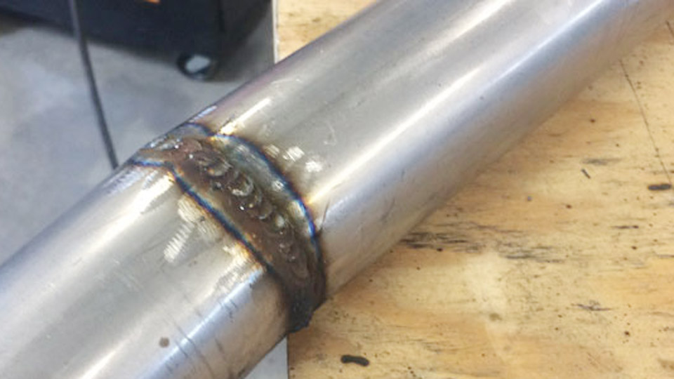
A malfunctioning welder can quickly turn a straightforward project into a series of failed welds, excessive spatter, poor penetration, or an unstable arc.
Knowing how to fix a MIG welder is essential because many common problems—such as inconsistent wire feeding, voltage irregularities, faulty ground connections, or worn consumables—can often be diagnosed and corrected without replacing the entire machine.
Addressing these issues early improves weld quality, reduces downtime, minimizes material waste, and helps prevent costly rework in both home workshops and professional fabrication environments.
Accurate troubleshooting also ensures the welder operates within its intended performance range, producing cleaner, stronger, and more consistent welds.
By understanding the most likely causes of MIG welder faults and applying the appropriate corrective steps, you can restore reliable machine performance and weld with greater confidence on your next project.
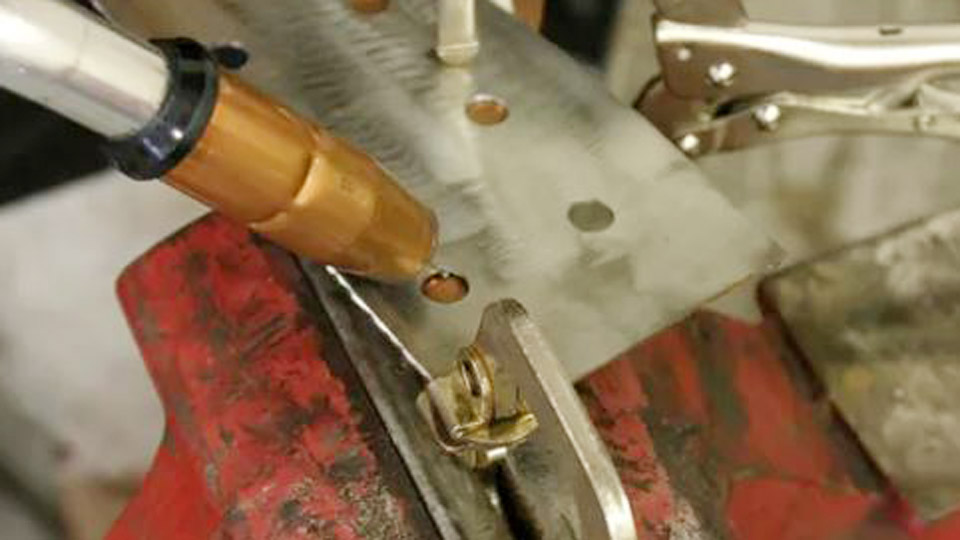
Image by hotrod
Diagnosing Power and No-Arc Issues
Input Voltage and Circuit Verification
MIG welders demand stable power matching their rated input. A 120V unit on a 15-20A circuit or a 230V model on a properly sized breaker can fail to deliver consistent voltage under load, preventing arc initiation even if the fan spins.
Measure voltage at the receptacle under load with a multimeter. Expect near-full rated voltage (e.g., 110-120V or 220-240V). Significant drops point to undersized extension cords, loose connections, or tripped breakers. Inspect the power cord for cuts, fraying, or corrosion at the plug.
Internal fuses or circuit breakers inside the welder may also blow from overloads or surges—consult the manual for replacement ratings, often slow-blow types.
Ground Clamp and Work Lead Integrity
Poor grounding ranks among the top reasons for no arc despite wire feeding. The clamp must make solid contact with clean, bare metal close to the weld zone (ideally within 12-18 inches) to minimize resistance.
Clean rust, paint, or scale from the contact area using a grinder or wire brush. Tighten the clamp securely. Test continuity from the clamp to the machine terminal if possible. Long runs on thick plate increase resistance; relocate the clamp or use heavier cable for better results.
Trigger Switch and Contactor Problems
Wire feeds but no arc often indicates the trigger switch or contactor isn’t energizing the welding circuit. Listen for the contactor click when pulling the trigger.
No click suggests wiring, switch, or control board issues. With power off, check trigger continuity with a multimeter. Worn switches common in high-use guns require replacement.
Resolving Wire Feed Problems
Drive Roll Tension, Groove, and Alignment
Incorrect drive roll setup causes slipping, stuttering, or birdnesting (wire tangling at the rolls). Match groove type and size exactly to wire diameter: V-groove for solid steel, U-groove for aluminum, knurled for flux-cored.
Set tension so the rolls grip firmly without deforming or shaving the wire. A practical test: release tension, pull wire by hand through the gun (tip removed), then re-tension until the wire stops when lightly pinched while the motor runs. Over-tension creates debris that clogs the liner; under-tension causes slippage and inconsistent amperage.
Gun Liner, Contact Tip, and Consumables
The liner transfers wire from feeder to gun. Kinks, debris, or wear create drag, leading to birdnesting or erratic feed. Remove the tip, straighten the cable, and pull wire by hand.
Heavy resistance means blow out the liner with dry compressed air or replace it. Trim liners squarely and ensure proper length.
Contact tips wear quickly. A bore that becomes oval or packed with spatter causes poor current transfer, burnback (wire fusing into the tip), and stubbing. Replace with the exact size for your wire (e.g., 0.030″ tip for 0.030″ wire).
Recess the tip 1/8″ to 1/4″ inside the nozzle for optimal gas coverage. Clean or replace the nozzle and diffuser regularly to prevent spatter buildup from restricting flow or causing turbulence.
Common Wire Feed Symptoms and Fixes
| Symptom | Likely Cause | Primary Fix |
|---|---|---|
| Birdnesting | High tension, blocked liner/tip | Loosen tension, clear path, replace liner |
| Burnback into tip | Low wire speed, short stickout, worn tip | Increase WFS, extend stickout to 3/8–1/2″, replace tip |
| Slipping/stuttering | Worn rolls, low tension, dirty wire | Match rolls, adjust tension, use clean wire |
| Wire stops mid-weld | Spool brake too tight, kinked liner | Adjust brake, inspect/replace liner |
Fixing Arc Instability and Sputtering
Voltage, Wire Feed Speed, and Parameter Balance
Erratic arcs with popping, excessive spatter, or stubbing usually stem from mismatched voltage and wire feed speed (WFS). Too low voltage for the WFS causes the wire to stub into the puddle; too high produces a long, unstable arc with undercut and spatter.
Consult your machine’s chart for baseline settings based on material thickness and wire diameter. For mild steel with 0.035″ wire on 1/8″ plate, typical ranges are 18-20V and 250-300 ipm WFS.
Fine-tune by sound: a steady “bacon frying” crackle indicates good short-circuit transfer. Test on scrap, adjusting one variable at a time—usually voltage in 0.5-1V increments.
Shielding Gas Flow and Coverage
Inconsistent gas delivery destabilizes the arc. Target 15-25 CFH for most applications, measured at the nozzle with a flowmeter (higher for spray transfer or larger nozzles). Check for leaks with soapy water at connections. Drafts over 5 mph disrupt coverage—use screens or reposition.
Porosity often follows poor gas: verify cylinder pressure, open valve fully, and ensure no restrictions in hoses or gun. Contaminated base metal (rust, oil, paint) requires cleaning to bright metal. Higher-silicon wires like ER70S-6 tolerate minor contamination better.
Polarity and Stickout Control
Solid wire with gas requires DCEP (electrode positive). Flux-cored self-shielded needs DCEN. Reversed polarity weakens or eliminates the arc. Maintain consistent stickout (3/8–1/2″ typical); excessive length reduces current density and shielding effectiveness, promoting burnback and porosity.
Addressing Weld Quality Defects
Porosity and Contamination Control
Porosity appears as holes or worm tracks from atmospheric contamination. Prioritize gas coverage, then metal cleanliness. Grind or brush to bright metal within 1-2 inches of the joint and wipe with acetone. Avoid drafts and excessive flow that causes turbulence.
Spatter buildup in the nozzle exacerbates this—clean frequently or apply anti-spatter. For repeated issues, inspect diffuser ports for blockages.
Spatter, Undercut, and Lack of Fusion
Excess spatter often results from voltage/WFS imbalance, dirty metal, or long stickout. Reduce voltage slightly or clean the joint.
Undercut (grooves at weld toes) comes from high voltage, fast travel, or poor torch angle—use 5-15° drag angle and slower travel to allow the puddle to fill edges.
Lack of fusion or cold lap indicates insufficient heat: increase voltage or WFS, slow travel, and ensure proper torch angle for sidewall fusion.
Overheating and Duty Cycle Management
Machines cutting out mid-weld often exceed duty cycle (e.g., 20% at max amps means 2 minutes on, 8 off). Ensure vents are clear of dust; failed fans require service. For prolonged use, drop amperage or allow cooling periods.
Maintenance Practices for Long-Term Reliability
Routine Consumable Replacement Schedule
Treat contact tips, nozzles, liners, and drive rolls as consumables. Replace tips at first signs of wear (oval bore, discoloration). Inspect liners every 50-100 hours or when drag increases. Clean drive rolls of shavings to prevent slippage.
Store wire in dry conditions to avoid rust. Use spool covers for outdoor or dusty environments.
Electrical and Mechanical Inspections
Periodically check internal connections for tightness and corrosion. Blow out dust from the machine interior. For advanced users, verify output with a load tester if arc performance degrades despite consumable changes.
When to Seek Professional Repair or Replacement
Persistent issues after checking power, grounding, consumables, gas, and settings may indicate deeper problems like failing transformers, control boards, or solenoids.
Gas solenoids that stick open/closed or feed motors with seized bearings often need specialized service. Weigh repair costs against a new machine’s features, especially for older units.
Decision-Making Summary
Effective MIG welder fixes prioritize the feed path (liner, tip, rolls), electrical return (ground), gas delivery, and parameter balance. Systematic checks—starting with basics like connections and consumables—resolve most issues quickly.
For pro-level insight, log successful settings for your common materials and thicknesses alongside consumable change intervals.
This data-driven approach minimizes guesswork, ensuring consistent penetration, bead profile, and productivity even under demanding shop conditions. Maintaining detailed records turns troubleshooting into preventive expertise.