Heat-sealed packages often fail when residual product, moisture, or film thickness variation causes incomplete fusion or burn-through. Operators then raise bar temperature or dwell time, which degrades heat-sensitive contents and slows cycle rates.
How does ultrasonic sealing work differently? High-frequency mechanical vibration generates frictional heat only at the material interface, melting thermoplastics in 100–200 milliseconds while the tooling remains cool.
This localized energy delivery produces hermetic seals through contaminants, reduces energy use, and maintains consistent strength on films, tubes, and molded parts.
For welders and fabricators moving into plastic packaging or hybrid assemblies, understanding the vibration-to-bond sequence determines whether the process delivers reliable production rates or requires constant parameter chasing.
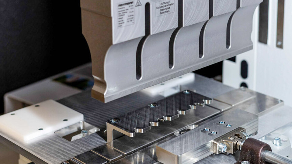
Image by herrmannultrasonics
Core Energy Conversion Sequence in the Ultrasonic Stack
Electrical line power must become controlled mechanical motion before any heat appears at the joint.
Generator-to-Transducer Conversion
The generator converts 50/60 Hz line voltage into a high-frequency electrical signal, typically 20 kHz, 30 kHz, or 40 kHz. This RF signal drives a piezoelectric transducer (converter).
Stacked ceramic discs expand and contract at the drive frequency, producing axial mechanical vibration with an initial amplitude of roughly 10–20 µm peak-to-peak.
Booster Amplification and Horn Delivery
A mechanical booster, clamped at a nodal point, multiplies or reduces that amplitude according to its gain ratio (commonly 1:1.5 to 1:2.5). The amplified vibration travels into the horn (sonotrode), a tuned titanium or aluminum tool whose face contacts the upper workpiece.
Horn geometry focuses energy into the desired seal pattern—linear, circular, or contoured. Final amplitude at the working face usually falls between 20 µm and 100 µm, depending on frequency and material thickness.
Pressure Application and Trigger Point
A pneumatic or servo actuator brings the horn into contact under controlled force. Ultrasound typically begins only after a preset trigger force is reached, ensuring consistent energy delivery regardless of minor part-height variation.
The anvil or fixture beneath the lower layer provides the reaction surface and often incorporates energy-focusing features such as knurls or raised edges.
Interface Friction and Localized Melting Mechanics
Heat does not conduct inward from hot tooling; it originates inside the polymer itself.
Molecular Friction Under Vibration
Once the horn vibrates, the upper layer oscillates relative to the lower layer at ultrasonic frequency. Surface asperities and intermolecular friction convert mechanical energy into heat within a few tens of milliseconds.
In amorphous resins the temperature rises rapidly past the glass-transition range; in semi-crystalline resins it must exceed the crystalline melting point.
Melting Zone Formation and Pressure-Assisted Flow
A thin molten film forms only at the contacting surfaces. Continued pressure forces the molten polymer to flow, interdiffuse molecular chains, and wet the interface.
Because the tools stay relatively cool, heat dissipates outward quickly once vibration stops. The short molten period limits thermal degradation of adjacent material or product contents.
Solidification Under Hold Force
After the programmed weld time or energy threshold, vibration ceases but force remains for a hold interval (typically 0.1–1.0 s).
The polymer resolidifies under compression, producing a molecular bond whose strength can approach that of the parent film. Hot-tack strength—immediate seam integrity before full cooling—is higher than most heat-seal methods because the melt is thinner and more uniformly pressurized.
Critical Process Parameters and Trade-Off Decisions
Four variables dominate seal quality: frequency, amplitude, force, and time/energy.
Frequency Selection by Part Size and Material
20 kHz systems deliver higher amplitude and power for larger seal areas or thicker sections. 30–40 kHz systems produce finer control, lower noise, and reduced marking on small or cosmetic parts. Higher frequency also couples better into thin films but attenuates more rapidly through thicker stacks.
Amplitude as the Primary Energy Driver
Amplitude sets the intensity of interfacial friction. Amorphous plastics (ABS, polycarbonate) typically run 30–70 µm; semi-crystalline materials (PP, PE, nylon) often require 40–100 µm or higher. Excess amplitude generates flash, burns the surface, or fatigues the horn. Insufficient amplitude yields cold welds with incomplete fusion.
Weld Force and Trigger Force Balance
Force must maintain intimate contact without squeezing molten polymer out of the joint before chain interdiffusion occurs. Typical ranges run 0.1–1 MPa or 100–3000 N depending on seal area. Trigger force (often 50–300 N) starts the ultrasound at a repeatable point in the down-stroke, improving process consistency across part variation.
Time, Energy, and Distance Control Modes
Time mode simply runs ultrasound for a fixed duration (0.1–2 s). Energy mode stops when a preset joule value is reached, compensating for small amplitude or force drifts.
Collapse (distance) mode monitors how far the horn travels as the joint melts and stops at a target collapse distance; this mode is preferred for validation because it directly measures melt displacement. Hold time after vibration allows solidification without rebound.
| Parameter | Typical Range | Primary Effect |
|---|---|---|
| Frequency | 20–40 kHz | Part size, marking, noise |
| Amplitude | 20–100 µm | Heat generation rate |
| Force | 100–3000 N | Contact, melt flow |
| Weld time | 0.1–2 s | Total energy input |
| Hold time | 0.1–1 s | Solidification under pressure |
Material Compatibility and Joint Geometry Requirements
Not every thermoplastic transmits ultrasonic energy equally.
Amorphous versus Semi-Crystalline Response
Amorphous resins (ABS, polystyrene, acrylic) damp vibration less and weld readily with standard energy directors. Semi-crystalline resins (polypropylene, polyethylene, polyamide) absorb more energy and require higher amplitude, nearer-field joints (horn close to the interface), and sharper energy directors or shear joints to concentrate stress.
Energy Directors and Shear Joints
A triangular energy director (0.2–0.6 mm high, 60–90° included angle) molded on one face concentrates stress and initiates melting at a precise line. Shear joints rely on interference fit and progressive melting along a vertical wall; they suit semi-crystalline materials and provide larger bond areas.
Tool-side focusing (knurled anvil or contoured horn) works for thin films where molded features are impractical.
Contaminants and Multi-Layer Films
Ultrasonic vibration can displace liquids, powders, or fibers from the seal zone, allowing hermetic bonds through product residue that would defeat heat sealing. Multi-layer barrier films seal successfully when the inner sealant layer is a compatible thermoplastic; the outer layers remain largely unaffected because heat generation is interfacial.
Performance Comparison Against Conventional Heat Sealing
Cycle time, energy, and seal consistency differ sharply.
Cycle Time and Throughput
Ultrasonic seals form in 100–200 ms of vibration plus brief hold, enabling higher machine speeds on form-fill-seal lines. Heat sealing requires longer dwell for conduction through the film and subsequent cooling of the bars.
Energy Consumption and Tool Temperature
Power is drawn only during the short ultrasonic pulse. Tools remain near ambient temperature, eliminating warm-up and reducing operator burn risk. Heat-seal bars must stay at elevated temperature continuously.
Seal Width and Material Savings
Ultrasonic seals can be as narrow as 2–3 mm while remaining strong, versus 8–12 mm typical for heat seals. Narrower seams reduce film consumption on high-volume packaging runs.
Sensitivity to Process Drift
Heat sealing depends on absolute bar temperature and contact pressure; small drifts produce under- or over-melting. Ultrasonic processes controlled by energy or collapse distance compensate for minor part or film variation more effectively.
Equipment Stack Integrity and Amplitude Stability
Long-term seal quality depends on maintaining stack resonance.
Stack Assembly and Torque
Converter, booster, and horn must be assembled at specified torque so nodal clamping points remain correct. Incorrect torque shifts resonant frequency and reduces available amplitude under load.
Amplitude Measurement and Feedback
Modern generators monitor power draw and can limit amplitude or stop the cycle if the load changes (horn wear, part misalignment). Peak-to-peak amplitude at the horn face should be verified periodically with an amplitude meter, especially after horn changes or heavy production.
Horn Material and Surface Condition
Titanium horns resist wear better than aluminum for abrasive films or filled plastics. Face textures or coatings must remain intact; worn surfaces reduce energy transfer and leave cosmetic marks.
Application Domains Where Ultrasonic Sealing Delivers Clear Advantage
Certain production constraints favor the process over alternatives.
Flexible Packaging and Tube Closing
Pouches, sachets, and plastic tubes (toothpaste, cosmetics, pharmaceuticals) benefit from contamination-tolerant seals and narrow seams. Cycle times support high-speed continuous motion or intermittent indexing lines.
Medical and Food Packaging
Low residual heat protects temperature-sensitive contents. Hermetic seals meet barrier requirements without adhesives or solvents.
Molded Plastic Assemblies
Housings, filters, and electronic enclosures use near-field or far-field welding with energy directors. The same stack technology that seals film also joins three-dimensional parts, giving fabricators a single process family.
Hybrid Metal-Plastic or Thin Metal Seams
While pure metal ultrasonic welding relies more on plastic deformation and oxide disruption than melting, thin foils and tube ends can be sealed with similar equipment when parameters are adjusted for higher force and shorter times.
Wrapping Up
Selecting ultrasonic sealing succeeds when the material transmits vibration, the joint can be designed for energy concentration, and the required seal area fits within practical horn size. Parameter windows are narrow for semi-crystalline films; amplitude and force must be validated on actual production material rather than generic charts.
Advanced users monitor real-time power curves and collapse distance to detect horn wear or film-lot changes before seal strength drops below specification.