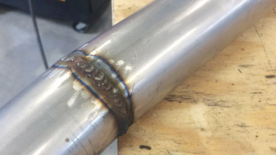
Burn-through on 18-gauge sheet or lack of fusion on ⅜-inch plate both stem from the same root cause: settings and technique locked to one thickness while the joint demands another.
Learning how to MIG weld different thickness metals means matching wire diameter, voltage, wire feed speed, transfer mode, and heat distribution to the actual heat sink of the joint.
Thickness controls required amperage, cooling rate, and whether a single short-circuit pass will fuse or whether bevels and multi-pass spray transfer become mandatory.
Incorrect pairing produces porosity, undercut, warping, or incomplete penetration long before visual inspection catches the defect. Accurate starting values plus position- and joint-specific adjustments eliminate the guesswork that wastes wire and scrap.
Image by mig-welding.co.uk
Selecting Wire Diameter by Thickness Range
Wire diameter sets the minimum stable amperage and deposition rate. Choosing too large a wire forces excess heat into thin material; choosing too small starves thick plate of filler and penetration.
Thin Sheet Metal: 24-Gauge to 16-Gauge
Use 0.023-inch or 0.030-inch ER70S-6. The smaller diameter melts at 30–90 A, keeping heat input low enough that the sheet can dissipate energy without melting through. 0.023-inch wire is preferred below 18 gauge; 0.030-inch becomes workable once thickness reaches 16 gauge.
Medium Plate: 14-Gauge to ⅛-Inch
0.030-inch or 0.035-inch wire covers this band. 0.030-inch remains controllable on the thinner end while still delivering enough filler for ⅛-inch single-pass fillets. 0.035-inch raises deposition and allows slightly higher travel speeds on the upper end of the range.
Heavy Plate: 3/16-Inch and Above
0.035-inch works up to roughly ¼-inch in short-circuit multi-pass. Beyond that, switch to 0.045-inch wire so the machine can reach spray-transfer currents without overheating the contact tip. 0.045-inch also raises deposition rate, reducing the number of passes required on beveled joints.
Core Voltage and Wire-Feed Settings for Mild Steel
Short-circuit transfer with 75 % argon / 25 % CO₂ (C25) is the default for thicknesses up to ¼ inch. Spray transfer with higher-argon mixes (90/10 or richer) becomes practical once plate thickness and machine capacity support it.
Short-Circuit Starting Chart (ER70S-6, C25, Flat Position)
| Thickness | Wire | Voltage | Wire Speed (IPM) | Approx. Amps | Gas (CFH) |
|---|---|---|---|---|---|
| 24 ga (0.024″) | 0.023–0.030″ | 14–16 V | 60–120 | 30–50 | 20–25 |
| 18 ga (0.048″) | 0.030–0.035″ | 15–17 V | 90–160 | 50–80 | 25–30 |
| 16 ga (0.060″) | 0.035″ | 16–18 V | 110–200 | 70–100 | 25–30 |
| 14 ga (0.075″) | 0.035″ | 17–19 V | 145–220 | 95–125 | 25–35 |
| ⅛″ (0.125″) | 0.035″ | 19–21 V | 200–260 | 135–160 | 25–35 |
| 3/16″ | 0.035″ | 19–22 V | 225–290 | 145–170 | 30–35 |
| ¼″ | 0.035″ | 19–22 V | 245–290 | 155–170 | 30–35 |
These values assume clean steel, ⅜–½-inch stick-out, and flat or horizontal position. Vertical-up and overhead require 10–20 % lower wire speed and roughly 1 V less to keep the puddle from sagging.
Spray-Transfer Window for Heavier Plate
On ¼-inch and thicker plate, 0.045-inch wire with 90 % argon / 10 % CO₂ can run 260–340 A at 26–30 V. Spray produces deeper penetration and higher deposition but is limited to flat and horizontal positions. Multi-pass short-circuit remains necessary for out-of-position work.
Technique Adjustments That Thickness Demands
Settings alone never produce a sound weld; travel speed, gun angle, and sequence must match the cooling characteristics of the material.
Controlling Heat on Thin Sheet
Stitch or skip welding prevents cumulative heat buildup. Lay ½–1-inch beads, pause long enough for the color to fade from red, then continue. Maintain a 5–15° push angle and travel 12–20 ipm so the puddle stays on the leading edge. Continuous beads on 18-gauge or thinner almost always create distortion or holes.
Achieving Full Penetration on Medium and Thick Plate
For ⅛-inch and above, a slight drag angle (5–10°) increases penetration. On butt joints thicker than ¼-inch, bevel both edges 30–37½° with a 1/16–⅛-inch root face and root opening.
Root passes run at the lower end of the amperage range; fill and cap passes can use higher wire speed once the groove is bridged. Interpass temperature should stay below 400 °F on mild steel unless a WPS specifies otherwise.
Joining Dissimilar Thicknesses
Set voltage and wire speed for the thicker member, then bias the arc toward that side. The thicker plate absorbs more heat; the thinner plate receives only the edge of the puddle.
A short pause on the thick side before rolling the arc onto the thin side equalizes fusion without burn-through. When the thickness ratio exceeds 2:1, consider a buttering pass on the thick edge first.
Transfer Mode and Gas Decisions Driven by Thickness
Short-circuit transfer remains stable down to the lowest amperages required by sheet metal and works in all positions. Globular transfer appears in the transition zone and produces high spatter; avoid it by either dropping into short-circuit or rising into true spray.
Spray transfer needs sufficient current density (roughly 175 A minimum for 0.035-inch wire on C10 gas) and is therefore practical only on ¼-inch and thicker material in flat or horizontal positions.
Gas flow stays 20–35 CFH for short-circuit. Spray requires 35–45 CFH to shield the larger, more fluid puddle. Drafty shops need an extra 5 CFH regardless of thickness.
Machine Capacity Limits That Restrict Thickness Options
A 120 V machine typically tops out near 140 A and is therefore limited to roughly 3/16-inch single-pass work or multi-pass on ¼-inch. 240 V machines rated 200–250 A open the door to spray transfer on ⅜-inch plate.
Duty cycle becomes the next constraint: continuous welding on thick plate quickly hits thermal limits on smaller units. For production work above ⅜-inch, a machine capable of 300 A continuous is the practical minimum.
Diagnosing Thickness-Related Defects from Bead Appearance
A ropey, high-crowned bead with poor toe fusion on thin material signals insufficient voltage or excessive wire speed relative to travel speed. Burn-through or excessive undercut indicates the opposite—heat input higher than the sheet can tolerate.
On thick plate, a shallow, wide bead with incomplete root penetration points to inadequate amperage or excessive stick-out. Cold lap at the toes of multi-pass welds usually means travel speed was too high or the previous pass was not cleaned thoroughly.
Decision Sequence for Any Thickness
- Measure the thinnest and thickest members in the joint.
- Select wire diameter that covers the required amperage band without forcing extremes.
- Start at the mid-range voltage and wire speed for the dominant thickness.
- Run a test coupon of identical thickness and joint geometry.
- Adjust voltage in 0.5 V steps and wire speed in 10–20 IPM increments until the arc produces a steady crackle and the bead wets evenly.
- For out-of-position or dissimilar-thickness joints, drop wire speed 10–15 % and re-test.
Wrapping Up
When the arc remains stable, the slag or oxide peels cleanly, and a cross-section shows full fusion without undercut or porosity, the combination of settings and technique is correct for that thickness.
Advanced operators further refine heat input by combining pulsed MIG (when available) with stringer beads rather than wide weaves, preserving mechanical properties on high-restraint or high-strength joints while still matching the thermal mass of each thickness in the assembly.
FAQs
What MIG settings work best for 1/8-inch mild steel?
Start with 0.035-inch ER70S-6 wire, 19–21 V, 210–260 IPM, C25 gas at 25–35 CFH. Expect roughly 135–160 A in short-circuit transfer.
How do I avoid burn-through when MIG welding 18-gauge sheet?
Use 0.023-inch or 0.030-inch wire, 15–17 V, 90–160 IPM, and stitch-weld in short segments with cooling pauses. Travel faster than on thicker plate and maintain a light push angle.
Can I MIG weld ⅜-inch plate with a 200-amp machine?
Yes, but expect multi-pass short-circuit or limited spray transfer. Bevel the joint, use 0.035- or 0.045-inch wire, and keep interpass temperature controlled. Duty cycle will limit continuous run time.
What wire size should I choose when joining 16-gauge to ¼-inch plate?
Select 0.035-inch wire and set parameters near the lower end of the ¼-inch range. Bias the arc toward the thicker plate so the thinner member receives only the edge of the puddle.