Overhead MIG welding is challenging because molten metal can sag or drip from the joint, making it difficult to maintain consistent penetration and a controlled weld bead. Understanding how to overhead weld MIG requires careful adjustment of voltage, wire feed speed, travel speed, and gun angle to keep the arc stable while limiting excessive heat buildup.
Settings that work well for flat welding may produce an oversized bead, poor fusion, or excessive spatter when welding overhead. These problems can compromise joint strength and increase the risk of weld defects, especially on thicker steel or structural components.
Proper technique also depends on material thickness, joint design, wire diameter, and the shielding gas being used. By choosing suitable machine settings and controlling the weld puddle, you can improve overhead weld quality, reduce rework, and achieve more consistent results without sacrificing fusion.
Image by weldcerttest
Machine Settings That Keep the Puddle Controllable
Overhead MIG succeeds or fails on heat input. The goal is a puddle small enough that surface tension and rapid solidification overcome gravity, yet hot enough for sidewall fusion.
Voltage and Wire-Feed Adjustments Relative to Flat Position
Start from a proven flat-position setting for the same thickness and wire diameter, then decide whether to hold or reduce. Many experienced operators run 85–95 % of flat heat because a cold arc produces a ropey bead that sits on the surface without fusion.
Others drop voltage 1–2 V and wire feed speed 10–15 % to shrink the puddle further. For ⅛-inch mild steel with 0.035-inch ER70S-6 wire, a common flat starting point is 18–20 V and 220–260 ipm.
Overhead often lands at 17–19 V and 200–240 ipm. Test on scrap of identical thickness; if the arc stubs, raise voltage first. If metal drips, lower wire speed or increase travel speed.
Short-Circuit Transfer as the Working Mode
Spray and globular transfer create large, fluid droplets that cannot stay overhead. Short-circuit transfer deposits tiny droplets with each brief short, freezing almost immediately. Confirm the machine is in the short-circuit voltage range (typically under 22–24 V for common solid wires).
Pulsed MIG can also work when available because it cycles between peak and background current, limiting average heat while still providing arc force.
Stickout Length and Its Direct Effect on Amperage
Contact-tip-to-work distance (CTWD) of ¼ to ⅜ inch is the practical window. Longer stickout increases electrical resistance, softens the arc, and lets the wire melt before it reaches the puddle—exactly the opposite of what overhead needs.
Keep the contact tip flush or slightly recessed so the arc stays tight and the force pushes metal into the joint rather than letting it hang.
Gun Angle and Work Position Decisions
Angle determines where the arc force is directed and whether the shielding gas stays effective.
Work Angle Versus Travel Angle
For a butt joint the gun sits nearly perpendicular to the plate (work angle ≈ 90°). For a T-joint fillet the work angle is roughly 45° so the arc reaches both plates equally. Travel angle stays small—5–15° push or drag.
Excessive push or drag lengthens the arc, reduces force, and invites undercut or cold lap. Point the gun slightly toward the upper plate on fillets to counteract gravity’s pull on the molten metal.
Bracing the Body for Consistent Distance
Freehand overhead work produces inconsistent stickout and wandering travel speed. Rest one hand or forearm against a solid surface whenever possible so the gun can move smoothly while CTWD remains fixed.
Position the body so the joint is visible without extreme neck strain; visibility of the leading edge of the puddle is more important than comfort alone.
Travel Technique and Motion Patterns That Prevent Sagging
Travel speed and motion pattern control how much metal is deposited before it freezes.
Steady Stringers Versus Controlled Weaves
Stringer beads keep the heat input lowest and the bead profile most predictable. A slight side-to-side or cursive-E motion can flatten the crown and improve toe fusion when the joint is wide, but the weave must stay tight. Large loops or long pauses allow the puddle to grow and drip.
Travel slightly faster than the equivalent flat bead so each increment of metal solidifies before the next is added.
Leading-Edge Arc Placement
Keep the arc on the leading edge of the puddle rather than sitting back in the molten pool. This forces fusion into the base metal and prevents the pool from overheating and falling. On multipass fillets, pause briefly at the upper toe to fill the undercut tendency that gravity creates.
Wire Diameter and Filler Choices for Overhead Control
Smaller wire diameters produce smaller puddles at lower total heat input and give finer control.
Preferred Diameters for Mild Steel
0.030-inch and 0.035-inch solid wire are the most common overhead choices. 0.045-inch wire can be used on thicker sections but demands tighter discipline on travel speed and stickout. Flux-cored wires with gas shielding can also perform well overhead when the procedure specifies them, provided the transfer mode remains controllable.
Shielding Gas Consistency
C25 (75 % argon / 25 % CO₂) remains the standard for short-circuit mild steel. Flow rates of 25–35 CFH are typical; higher flow is unnecessary and can create turbulence that pulls air into the shield.
Pure argon is required for aluminum, and the same short-stickout, reduced-heat logic applies, although aluminum’s high thermal conductivity often needs more absolute heat than steel of the same thickness.
Joint Design and Thickness Considerations
Different joints absorb heat and respond to gravity differently.
Fillet Welds Versus Groove Welds
Fillet joints allow the arc to be aimed into the root while the upper plate supports the puddle. Groove welds require more precise root-pass technique; a slightly colder setting and faster travel help keep the root from falling through an open root.
On multipass work, clean thoroughly between passes—overhead slag or spatter is harder to remove and more likely to cause inclusions.
Thickness-Driven Starting Points
For material under ⅛ inch, stay at the lower end of the short-circuit range and consider stitch welding to limit heat. On ¼-inch and thicker plate, multiple stringer passes with interpass cleaning produce stronger results than one large, overheated bead. Always match wire diameter and total heat input to the thinnest member in the joint.
Reading the Bead to Diagnose Parameter Errors
Visual feedback arrives faster than any meter.
Signs the Heat Is Too High
Excessive crown that sags, undercut at the toes, heavy spatter raining downward, and a loud, explosive arc all indicate the puddle is too fluid. Reduce wire feed speed or voltage, or increase travel speed immediately.
Signs the Heat Is Too Low
A ropey, stacked bead with poor sidewall fusion, frequent stubbing, and a weak arc sound mean the settings are too cold or the stickout is too long. Raise voltage first, then wire speed if needed, while keeping CTWD short.
Surface Appearance Targets
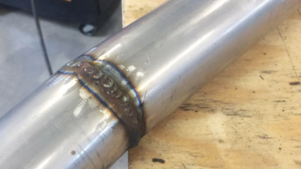
A successful overhead bead shows uniform ripples, equal leg lengths on fillets, smooth toe transitions, and minimal reinforcement. Cross-section etch tests on practice coupons confirm fusion depth that surface appearance alone cannot reveal.
Equipment and Consumable Details That Affect Consistency
Contact tips wear faster overhead because of the longer duty cycle and spatter exposure. Replace tips at the first sign of oval wear. Nozzle cleanliness matters more than in flat position; spatter buildup changes gas flow and stickout. Use anti-spatter compound sparingly so it does not contaminate the weld.
Drive-roll tension and liner condition must be perfect—any hesitation in wire feed produces an unstable arc that is far harder to recover from overhead.
Final Thoughts
Overhead MIG becomes reliable once voltage, wire speed, stickout, and travel speed are treated as a single system rather than independent knobs. The decision that separates acceptable beads from rejected ones is whether the puddle stays small enough to freeze before gravity wins, while the arc still carries enough force for fusion.
Advanced operators further refine results by matching pulse parameters (when available) to joint thickness so peak current drives penetration and background current keeps the average heat low enough for overhead control.