
A weld that looks uniform on the surface can still fail bend tests or ultrasonic inspection when the deposited metal geometry is wrong. Operators frequently confuse a welding bead with the finished joint and select the wrong deposition pattern, producing excessive heat input, incomplete fusion at the toes, or a heat-affected zone that softens high-strength steel.
Understanding what is a welding bead and its types directly controls penetration profile, residual stress, and whether a procedure qualification record will pass.
The bead is the single continuous deposit of fused filler and base metal created in one pass; its width, height, and internal structure determine how subsequent passes interlock and how much distortion the assembly absorbs.
Choosing stringer versus weave, or a process-specific motion, is a technical decision that must match joint geometry, position, material grade, and code limits on heat input.
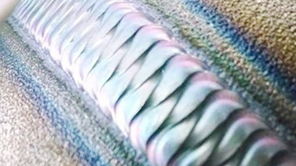
Image by weldingwizzard
How Bead Geometry Controls Strength and Heat Distribution
Bead shape is not cosmetic. Cross-section measurements dictate stress concentration, throat thickness in fillets, and the volume of metal that must be reheated by later passes.
Convex, Flat, and Concave Profiles in Practice
A convex bead presents a raised crown and is common with high-current stick or short-circuit MIG. It increases reinforcement but can create sharp notches at the toes if the transition is abrupt, raising fatigue risk under cyclic loading.
Flat beads balance reinforcement and fusion; most structural procedures target a nearly flat face with smooth toe blending. Concave beads appear frequently in vertical-up fillets or when voltage is high relative to travel speed.
They reduce throat thickness and can leave undercut that must be repaired before the next pass. Measurement of face height and leg size with a weld gauge confirms whether the deposited metal meets the required effective throat.
Bead Width Relative to Electrode or Wire Diameter
For SMAW, a practical rule places stringer width at roughly two to three times the core-wire diameter. Wider deposits move into weave territory and raise heat input per unit length. In GMAW the same relationship holds with wire diameter, although spray transfer produces naturally flatter profiles at higher currents.
Exceeding four to six times the electrode diameter in a single pass often produces slag inclusions or incomplete fusion at the sidewalls because the arc energy is spread too thinly. Codes and welding procedure specifications frequently limit maximum weave width precisely to keep heat input inside qualified ranges.
Stringer Bead Technique and the Conditions That Favor It
A stringer bead is deposited with essentially linear travel and minimal lateral oscillation. The arc remains concentrated, producing deeper penetration relative to deposited volume and lower overall heat input.
Typical Width, Travel Speed, and Parameter Windows
On 1/8-inch E7018 in the flat position, a stringer commonly runs 110–140 A with travel speeds of 6–9 inches per minute, producing a bead ¼ to ⅜ inch wide. The same electrode in vertical-up may drop to 105–120 A and slower travel to maintain puddle control.
In GMAW short-circuit mode on 0.035-inch wire, stringers at 18–22 V and 150–200 A keep the bead narrow and the heat-affected zone tight. The absence of oscillation reduces the time the arc spends on any one location, limiting grain growth in the HAZ.
Heat-Input Advantages on High-Strength and Quenched Steels
Many pressure-vessel and structural steel procedures restrict or prohibit wide weaves because the additional heat softens the base metal or enlarges the softened zone adjacent to the fusion line. Stringers allow multiple narrow passes that each contribute less cumulative heat.
When a welding procedure specification lists a maximum heat input in kJ/in, stringers make compliance easier because travel speed can remain higher for a given amperage.
In multipass groove welds the stacked stringers also create more interpass fusion surfaces, which can improve resistance to lamellar tearing under high restraint.
Weave Bead Patterns and the Trade-Offs They Introduce
A weave bead uses deliberate transverse oscillation while progressing along the joint. The motion widens the deposit and increases deposition rate per linear inch, but it also raises heat input and changes solidification patterns.
Zigzag and Crescent Motions for Horizontal and Flat Joints
Zigzag oscillation moves the arc from one sidewall to the other with brief pauses at the toes to ensure fusion. Crescent or “C” motions keep the arc on the leading edge of the puddle and are useful for controlling undercut on horizontal fillets.
Both patterns work well when the groove is wide enough that several stringers would be required. Travel speed is reduced relative to a stringer so that the side-to-side motion still produces adequate thickness; typical weave widths stay under ¾ inch unless the procedure explicitly qualifies a wider deposit.
Triangular and Circular Patterns for Vertical and Overhead Control
Vertical-up weaving often employs a triangular path that builds a shelf of solidified metal under the puddle, counteracting gravity. Circular or curlicue motions distribute heat more evenly and can reduce the tendency for the molten pool to sag.
These patterns demand consistent oscillation frequency; too slow and the edges lack fusion, too fast and the center becomes convex and undercut appears at the toes. Overhead weaves are kept narrow because excess width increases the volume of unsupported liquid metal.
Code and WPS Limits on Weave Amplitude
AWS D1.1 and many ASME Section IX procedures define or restrict maximum weave width. A common practical limit is three to five electrode diameters; beyond that the deposit is treated as a weave that must be separately qualified if heat input exceeds the original procedure range.
Inspectors measure the finished bead face; a deposit wider than the qualified maximum can force repair or requalification even when visual appearance is acceptable.
Process-Specific Motions That Alter Bead Formation
Certain electrode or torch manipulations are tied to process characteristics and produce distinctive bead surfaces.
Whip Motion with Cellulosic Stick Electrodes
The whip-and-pause technique used with E6010 or E6011 electrodes advances the arc briefly out of the puddle then returns. The motion allows the keyhole to form and solidify in controlled steps, producing the classic “stacked dime” or ripple pattern on open-root pipe welds.
Amperage is typically set at the lower end of the electrode range so the puddle freezes quickly during the whip. Excessive whip distance creates lack of fusion; insufficient whip leaves a continuous keyhole that collapses.
Walking the Cup in TIG Pipe Root and Hot Passes
In orbital or manual TIG pipe welding the cup rests against the joint and is rotated in a small arc while the filler is added. The technique maintains a fixed electrode-to-work distance and produces a uniform, tightly spaced ripple pattern.
Torch angle and rotation speed control the amount of reinforcement; too aggressive a walk widens the bead and risks suck-back on the root. Walking the cup is limited to positions where the cup geometry can contact both sides of the joint consistently.
Multi-Pass Build-Up Choices Between Stringers and Weaves
Once the root is complete, fill and cap passes require a decision between multiple narrow stringers or fewer wider weaves.
Interpass Fusion and Cleaning Requirements
Each stringer creates additional fusion interfaces that must be cleaned of slag or oxide. Incomplete removal produces elongated inclusions that ultrasonic testing will reject.
Wide weaves reduce the number of interfaces but leave a larger volume of slag that must still be removed completely. On low-hydrogen processes the cleaning interval also controls moisture absorption and hydrogen pickup between passes.
Managing Heat-Affected Zone Softening and Distortion
Stacking many stringers keeps peak temperatures lower in any single location and can preserve hardness in quenched-and-tempered steels. Wide weaves deposit more heat in fewer passes, increasing the risk of HAZ softening and higher residual stress.
When distortion control is critical, stringers combined with balanced sequencing around the joint minimize angular change. Procedure qualification records that list both techniques must demonstrate that the mechanical properties remain within specification for each approach.
Diagnosing Parameter Errors Directly from Bead Surface and Cross-Section
Bead appearance supplies immediate feedback on travel speed, oscillation consistency, and heat balance.
Surface Indicators of Travel Speed and Oscillation Problems
A ropey, high-crowned bead with poor toe fusion usually indicates travel that is too slow or amperage that is too low relative to the chosen motion. Undercut along both toes combined with a flat or concave face points to excessive travel speed or voltage that is too high.
Irregular ripples or cold-lap at the edges of a weave reveal inconsistent oscillation amplitude or pause time at the sidewalls. Cross-sectioning a test coupon reveals whether the fusion line is complete and whether the reinforcement height stays inside code limits.
Wrapping Up
Selecting the correct bead type is a balance of required fusion, allowable heat input, joint access, and code constraints. Stringers dominate when heat input must stay low and penetration is the priority; controlled weaves accelerate fill on wide joints provided the procedure qualifies the additional heat.
Process-specific motions such as the whip or cup walk exist because they solve puddle-control problems that pure stringer or weave techniques cannot address alone.
Advanced operators further refine results by measuring actual heat input in kJ/in on every qualified procedure and adjusting oscillation frequency so that the solidification front remains consistent from start to crater, eliminating the need for extensive grinding or repair on critical joints.
FAQs
What is the difference between a stringer bead and a weave bead?
A stringer is deposited with minimal side-to-side motion and stays roughly 2–3 electrode diameters wide; a weave uses deliberate transverse oscillation and produces a wider deposit with higher heat input per unit length.
When should I use a weave bead instead of stringers?
Use a controlled weave when the joint is wide enough that multiple stringers would be inefficient and the welding procedure permits the resulting heat input, typically on thicker plate in the flat or horizontal position.
What does a good welding bead look like?
A sound bead shows uniform ripples, smooth toe blending without undercut, consistent width, and a face profile (flat to slightly convex) that meets the required reinforcement height for the joint type.
Can I weave with 7018 electrodes in vertical position?
Yes, but keep the weave narrow and use a triangular or crescent pattern that builds a supporting shelf; many procedures still prefer stringers for vertical-up 7018 to limit heat input and maintain better sidewall fusion.


