Wire that refuses to feed, birdnests at the drive rolls, or stutters mid-bead stops production on any Hobart MIG machine. Fixing Hobart welder wire feed problems starts with isolating the exact restriction or electrical fault rather than randomly swapping parts.
Drive-roll tension, liner drag, contact-tip condition, and spool-brake settings account for the majority of failures on Handler 140, 190, IronMan, and similar models. Incorrect diagnosis wastes consumables and risks motor overload or burnback.
Systematic checks of the mechanical feed path first, followed by trigger and control-board verification, restore consistent wire delivery and stable arc performance across solid and flux-cored wires.
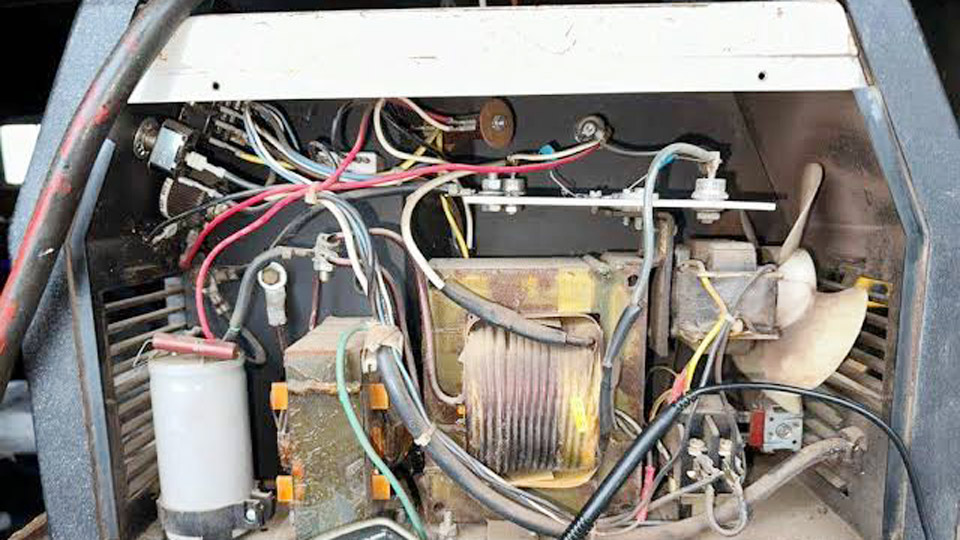
Image by weldingweb
Diagnosing Complete Loss of Wire Feed
When the trigger is pulled and the fan runs but no wire exits the contact tip, the fault lies in the mechanical path, trigger circuit, or motor power.
Confirm Spool, Hub, and Inlet Guide Condition
Open the side panel and verify the spool still contains wire and rotates freely. Crossed wraps or a seized hub create immediate binding.
Spool-brake tension that is set too high adds continuous drag; loosen the hub nut one-quarter turn at a time until the spool stops within one to two seconds after trigger release yet still turns under light hand pull.
Inspect the inlet guide for debris or misalignment that scrapes the wire before it reaches the drive rolls.
Test Trigger Continuity and Motor Response
Disconnect the gun trigger leads at the machine terminals and briefly short the connectors. If the drive motor runs, the gun switch or lead is open—common after two to three years of use on Handler models.
Measure voltage at the motor terminals with the trigger closed; expect 12–24 VDC at mid-range speed settings. Zero voltage with a good trigger points to a tripped PTC thermistor or failed control-board component on 135/140/175 units.
Verify Drive-Roll Rotation Without Load
Remove the contact tip and nozzle. Pull the trigger with the gun cable straight. If the rolls turn but wire does not advance, the problem is downstream restriction or incorrect groove engagement. If the rolls remain stationary, the motor, gearbox, or power circuit requires further isolation.
Correcting Birdnesting at the Drive Rolls
Birdnesting—wire coiling and tangling behind the drive rolls—occurs when push force exceeds downstream resistance or when the rolls slip.
Set Proper Drive-Roll Tension
Fully loosen the tension knob. Thread wire through the inlet guide and into the correct groove. Tighten gradually while feeding at 40–50 % speed until the wire can be stopped by firm hand pressure at the tip without crushing or flattening.
Add one-quarter to one-half turn more. Excess tension deforms soft 0.030–0.035 in. solid wire and generates metal flakes that clog the liner. Insufficient tension allows backlash and nesting on the next start.
Match Groove Style and Diameter Exactly
Handler dual-groove rolls are stamped .030/.035. Use the smooth V-groove for solid mild-steel or stainless wire. Flip the roll for the knurled (VK) groove when running flux-cored wire.
A size mismatch increases friction 20–30 % and forces the motor to work against resistance. Replace rolls once grooves flatten or after 500–1,000 lb of wire, whichever comes first.
Eliminate Downstream Restrictions That Force Nesting
A clogged contact tip or kinked liner creates the back-pressure that turns normal feed into a birdnest. Remove the tip and attempt hand-feeding; any grinding or sticking confirms liner or tip blockage. Cut out the nest only after power is disconnected, then re-thread with the cable fully straight.
Resolving Inconsistent or Jerky Wire Feed
Stuttering, surging, or sudden stops produce uneven beads and frequent burnback.
Clean or Replace the Gun Liner
Liners accumulate wire coating residue, grinding dust, and spatter. Blow compressed air (30–40 psi) from the diffuser end toward the feeder. If resistance remains above 2–3 lb when pulling wire by hand with the tip removed, replace the liner.
Cut new liners square, deburr both ends, and seat them flush in the diffuser with zero gap. Too-short liners allow buckling; too-long liners kink at the connection. Steel liners suit mild-steel wire; Teflon or plastic-lined versions are mandatory for aluminum and recommended for stainless.
Inspect and Replace Worn Contact Tips
An oval or keyholed tip bore creates erratic current transfer and intermittent arc length. Replace tips every 50–100 lb of wire or at the first sign of burnback. Match tip bore exactly to wire diameter—0.030 in. tip for 0.030 in. wire, never oversized. Maintain ⅜–½ in. stick-out for stable current transfer.
Check Spool Drag and Cable Routing
Excessive hub brake tension or a tightly coiled gun cable increases drag. Route the gun lead in large, smooth loops; sharp bends raise friction dramatically. Verify the wire lies fully in the drive-roll groove and that the inlet guide sits as close as possible to the roll without contact.
Addressing Burnback and Contact-Tip Related Feed Stops
Burnback melts the wire into the tip, locking the feed path.
Balance Voltage and Wire-Feed Speed
Excessive voltage relative to wire speed causes the arc to climb the wire and fuse it inside the tip. Reduce voltage one to two settings or increase wire speed slightly until the arc remains at the tip face.
On Handler 140/190 machines running 0.030 in. solid wire and C25 gas, typical mid-range settings for ⅛–¼ in. mild steel fall between door settings 3–5 and wire-speed dials 40–60, but always confirm with a test bead.
Clear Spatter and Maintain Diffuser/Nozzle
Spatter fused inside the tip or on the diffuser restricts both wire and gas. Clean nozzles with a reamer or pliers and apply anti-spatter compound sparingly. A blocked diffuser also starves the arc of shielding, compounding feed inconsistency through unstable arc force.
Electrical and Thermal Causes of Feed Interruption
Some failures occur only after minutes of welding or under load.
PTC Thermistor and Overheat Protection
On Handler 135/140/175 models the PTC thermistor opens when the motor overloads from prolonged restriction. The feed stops after several seconds even though the fan continues.
Allow 10–15 minutes of cooling with the fan running, then eliminate the mechanical restriction that caused the overload. Permanent failure requires the PTC1 replacement kit.
Duty-Cycle and Thermal Shutdown
Handler 140 is rated approximately 90 A at 20 % duty cycle. Exceeding this limit trips the thermostat. Respect rated output and improve ventilation; clean internal dust that restricts airflow. After cooling, resume at lower settings or shorter arc times.
Speed-Control Potentiometer and Board Issues
Erratic speed or locked full-speed feed often traces to a worn potentiometer or failed TIP142 transistor. A healthy 10 kΩ pot sweeps linearly; jumps or open sections require replacement. Direct 12 V DC applied across the motor terminals confirms whether the motor itself still runs.
Model-Specific Patterns on Popular Hobart Machines
Different Handler and IronMan platforms show recurring failure modes.
Handler 140 and 135 Series
Undersized motors and rapid liner clogging appear frequently. Keep tension light, trim liners short, and replace the PTC at the first intermittent-stop symptoms. Dual-groove rolls must be flipped correctly when changing between solid and flux-cored wire.
Handler 190 and Higher-Duty Units
Drive-roll bearings wear under sustained use. Genuine Hobart roll kits restore smooth rotation. Trigger switches become sticky after heavy duty cycles; cleaning or full switch replacement restores reliable contact.
IronMan and Larger Feeders
Trigger-switch failures and occasional plastic tension-arm cracking occur. Metal-arm upgrades and routine switch cleaning prevent recurrence. Longer gun cables demand more attention to liner condition and cable routing.
Systematic Decision Sequence for Any Feed Fault
Begin with the mechanical path because 70–80 % of Hobart wire-feed problems resolve there without electrical testing. Confirm spool rotation and hub drag, verify correct groove and tension, remove the contact tip and hand-pull the wire, then inspect and clean or replace the liner.
Only after the path is free should trigger continuity, motor voltage, and board components be examined. Record model, serial, wire diameter, and gas type before ordering parts—production changes mean identical model names may use different drive assemblies or control boards.
Wrapping Up
A clean, correctly tensioned feed path with matched consumables delivers consistent wire speed, stable arc length, and predictable penetration.
Once mechanical drag is eliminated and electrical continuity confirmed, the remaining variables—voltage, wire speed, and travel technique—produce repeatable results rather than masking an underlying restriction.
Advanced operators further reduce downtime by logging liner replacement intervals against pounds of wire consumed and by keeping a spare dual-groove roll and contact-tip assortment matched to the wire sizes used most often.
FAQs
Why does my Hobart Handler wire feed stop after a few seconds?
A tripped PTC thermistor or thermal overload from liner drag or excess drive-roll tension is the usual cause. Cool the machine, clear the restriction, and replace the PTC if the fault recurs immediately.
How do I stop birdnesting on my Hobart MIG welder?
Reduce drive-roll tension until the wire can be stopped by hand at the tip, confirm the correct groove for solid or flux-cored wire, and replace any kinked or dirty liner.
What causes jerky or inconsistent wire feed on a Hobart Handler?
Dirty or worn liner, incorrect contact-tip size, or mismatched drive-roll groove create variable drag. Clean or replace the liner and tip, then recheck tension with the gun cable straight.
Can I run flux-cored wire on the same drive rolls as solid wire?
Yes, but only if the roll is dual-groove. Flip to the knurled side for flux-cored wire; the smooth V-groove will slip and produce birdnesting or incomplete feed.