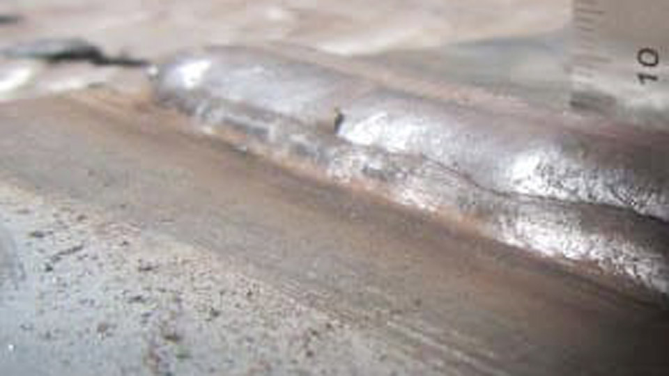
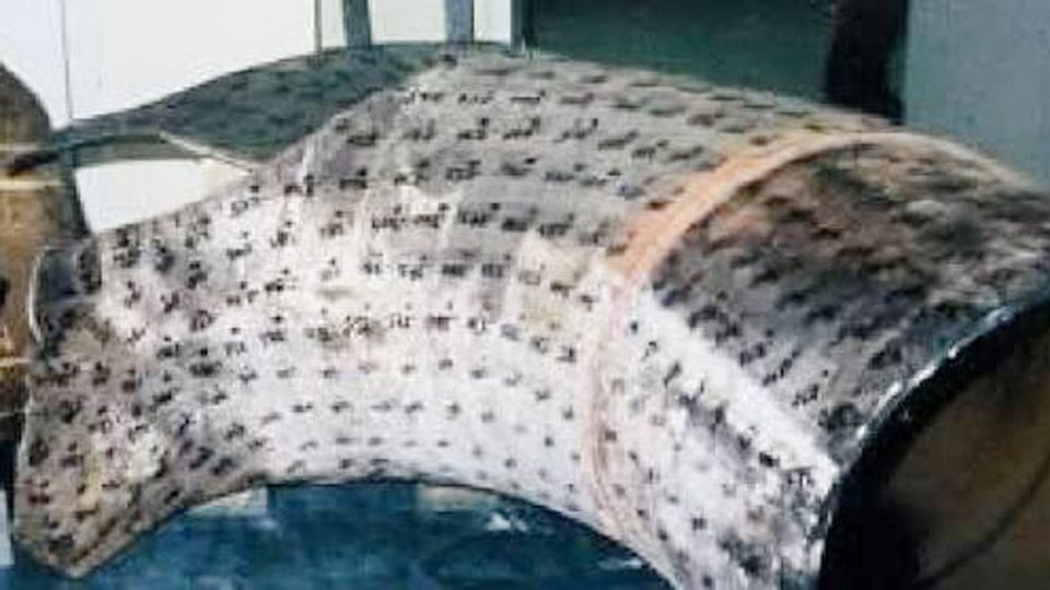
A clean-looking MIG bead that fails a bend test or shows internal holes after grinding is one of the most frustrating shop experiences. The arc sounded fine, the wire fed, yet the finished weld contains porosity, heavy spatter, or incomplete fusion.
These common MIG welding issues and how to fix them determine whether a joint meets structural requirements or becomes scrap.
Incorrect gas coverage, mismatched voltage and wire-feed speed, contaminated base metal, or excessive stick-out each produce distinct defects that weaken tensile strength, invite cracking, and increase rework time.
Addressing the root cause with measurable parameter changes—rather than random knob turns—restores consistent fusion, bead profile, and mechanical properties on mild steel, stainless, and aluminum.
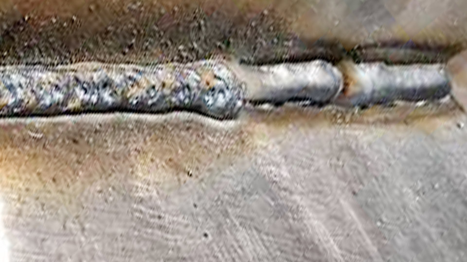
Image by millerwelds
Porosity That Appears as Surface Holes or Subsurface Voids
Porosity forms when atmospheric gases or contaminant vapors become trapped in the solidifying weld pool. Nitrogen and oxygen from air produce the most frequent defects; hydrogen from moisture or hydrocarbons creates elongated worm-track porosity.
Shielding-Gas Coverage Failures
Inadequate coverage is the dominant cause. Flow rates below 20 CFH leave the pool unprotected; rates above 40–50 CFH create turbulence that draws air into the gas column. Measure flow at the nozzle orifice, not the regulator. Typical indoor settings for 0.030–0.035 in solid wire run 20–30 CFH with 75/25 argon-CO₂.
Outdoor or drafty conditions may require a modest increase plus wind barriers. Leaks in hoses, fittings, or the gun solenoid produce the same result as low flow—inspect with soapy water and replace cracked lines. A clogged diffuser or spatter-packed nozzle restricts laminar flow; clean or replace both regularly.
Base-Metal and Wire Contamination
Rust, mill scale, oil, paint, and moisture release gases when heated. Grind or wire-brush to bright metal within at least 1 in of the joint edges. Wipe residual oils with acetone or isopropyl alcohol; avoid chlorinated solvents that form toxic compounds under the arc.
Galvanized coatings generate severe porosity and zinc fumes—remove the coating completely in the weld zone. Wire stored in humid conditions absorbs moisture; keep spools sealed or in a dry cabinet.
Higher-silicon ER70S-6 wire tolerates light residual scale better than ER70S-3 because the additional deoxidizers scavenge oxygen.
Stick-Out Length and Gun Technique
Contact-tip-to-work distance longer than ½ in reduces gas effectiveness and increases resistance heating of the wire. Maintain ⅜–½ in stick-out for short-circuit transfer.
Excessive push angles or travel speeds that outrun the gas envelope also introduce air. Keep the nozzle roughly ¾ in from the puddle and use a 0–15° travel angle so the gas column remains centered over the pool.
Excessive Spatter and Popping Arc Behavior
Spatter appears as scattered metal droplets that require grinding and indicate unstable metal transfer. Short-circuit transfer always produces more spatter than spray or pulsed modes, but correct parameters keep it manageable.
Voltage-to-Wire-Feed Mismatch
Voltage controls arc length; wire-feed speed (WFS) controls amperage and deposition. Voltage too low relative to WFS causes the wire to stub into the puddle and explode droplets outward—the classic loud popping sound. Voltage too high produces a long, harsh arc with fine spatter and undercut.
For 0.035 in wire on ⅛ in mild steel, a common short-circuit window is 17–20 V at 200–280 ipm. Listen for a steady “frying bacon” sizzle. Adjust in 0.5 V or 10–20 ipm increments while watching the transfer.
Spray transfer (higher argon mixes, typically above 22–24 V and corresponding higher WFS) dramatically reduces spatter once the transition current is reached.
Contact Tip, Stick-Out, and Ground Path
A worn, oversized, or loose contact tip creates intermittent electrical contact and erratic arc force. Replace tips at the first sign of pitting or keyholing; match the orifice exactly to wire diameter. Stick-out beyond ½ in increases circuit resistance, drops effective amperage, and destabilizes the arc.
A poor work-clamp connection—painted, rusty, or distant from the weld—produces voltage drop and the same unstable behavior. Clamp on clean metal as close to the joint as practical.
Surface Condition and Gas Effects
Dirty base metal or contaminated wire introduces vapor that disrupts the arc. Higher CO₂ percentages increase spatter compared with 75/25 or 90/10 argon blends. Confirm polarity is electrode positive (DCEP) for solid wire; reversed polarity produces heavy spatter and poor penetration.
Lack of Fusion and Cold Lap at the Toes or Sidewalls
Lack of fusion leaves unmelted base metal or previous bead surfaces; cold lap is the related condition in which filler sits on top without wetting. Both create stress risers and reduce load capacity.
Insufficient Heat Input
Low voltage or WFS fails to melt the sidewalls adequately. On ¼ in plate with 0.035 in wire, raise settings into the 20–23 V and 250–350 ipm range to reach 180–220 A.
Short-circuit transfer inherently limits penetration; move to globular or spray when thickness and joint access allow. Dirty or oxidized surfaces act as barriers—clean to bright metal before increasing heat.
Gun Angle and Arc Position Relative to the Puddle
A steep drag angle or “riding the pool” (arc lagging behind the leading edge) deposits metal onto unmelted surfaces. Maintain a 5–15° push angle and keep the arc on the leading edge of the puddle.
Travel speed that is too fast for the chosen parameters starves the sidewalls of heat; slow enough to allow the pool to wet both edges without excessive reinforcement.
Wide weaves that dwell too long in the center and leave the toes cold produce the same defect—narrow the oscillation or switch to stringers.
Burn-Through on Thin-Gauge Material
Burn-through occurs when heat input exceeds the material’s ability to conduct energy away, melting a hole through the sheet. It is most common below ⅛ in or 12–16 gauge.
Parameter Reduction and Travel Speed
Drop voltage 1–2 V and reduce WFS proportionally. For 16–18 gauge with 0.030 in wire, start near 15–17 V and 120–180 ipm. Increase travel speed to 18–25 ipm so heat does not accumulate in one location.
Stitch or skip welding further limits localized heating. Smaller-diameter wire (0.023–0.030 in) lowers current for a given WFS and helps control the pool on thin stock.
Fit-Up, Backing, and Heat-Sink Techniques
Large root gaps concentrate heat and promote melt-through. Keep gaps under 1/16 in or use copper backing bars that draw heat without fusing to the weld. Pulse modes on modern machines reduce average heat input while maintaining fusion.
Aluminum requires even tighter control because of its high thermal conductivity and lower melting point—pure argon, 4043 or 5356 wire, and faster travel are mandatory.
Undercut Grooves Along the Weld Toes
Undercut is a continuous or intermittent groove melted into the base metal beside the bead and left unfilled. It reduces cross-section and acts as a fatigue initiator.
Excess Heat and Travel Speed
Voltage that is too high lengthens the arc and digs into the toes. Travel that is too fast leaves the molten metal unable to fill the melted edge. Reduce voltage in 0.5 V steps and slow travel until the pool wets and fills the toes. Excessive weave width or failure to pause briefly at each edge produces the same result—tighten the oscillation.
Work Angle and Joint Geometry
An incorrect work angle directs more arc force into one plate, melting a groove while under-filling the opposite side. For T-joints, balance the angle so both legs receive equal heat. High-CO₂ gas mixes increase fluidity and undercut tendency; switching to higher-argon blends improves surface tension and bead control.
Wire-Feed Disruptions: Bird-Nesting, Stubbing, and Burn-Back
Mechanical feed problems interrupt the arc, produce irregular beads, and damage consumables.
Drive-Roll Tension, Liner Condition, and Spool Brake
Bird-nesting (wire pile-up behind the drive rolls) results from excessive drive-roll pressure, a restricted liner, or a spool brake that is too tight. Set tension just high enough that the wire does not slip when the gun is held vertical and the trigger is pulled.
Inspect and replace liners that show shavings or kinks; cut the liner to the exact length specified for the gun. Spool brake should allow free rotation with minimal drag.
Contact-Tip and Stick-Out Interactions
Stubbing occurs when WFS is too low for the voltage or the tip is partially blocked—the wire pushes into the plate without melting. Burn-back (wire fusing inside the tip) occurs when WFS is too low, stick-out is excessive, or the tip is worn.
Increase WFS slightly, shorten stick-out to ⅜–½ in, and replace any tip that shows wear or spatter buildup. Correct drive-roll groove size (V-groove for solid wire, knurled for flux-cored) prevents deformation that leads to erratic feed.
Wrapping Up
Consistent diagnosis follows a fixed order: verify gas delivery and metal cleanliness first, then confirm contact tip and ground path, then balance voltage against WFS while holding stick-out constant.
Once those variables are stable, technique adjustments for angle and travel speed resolve the remaining fusion and profile defects.
Advanced operators further reduce variability by recording exact parameter sets for each material thickness and joint type, then using synergic or pulse programs to lock the relationship between voltage and wire speed.