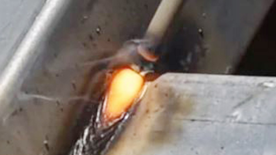
Most attempts at welding cast iron to steel with 7018 end in cracking within hours or days. The high carbon content of gray cast iron (typically 2–4 %) forms hard, brittle martensite in the heat-affected zone when mixed with the low-hydrogen steel deposit from a 7018 electrode.
At the same time, the two metals expand and contract at different rates, locking residual stress into the joint. The result is a weld that looks solid on the bench but fails under vibration, thermal cycling, or modest tensile load.
Understanding exactly when 7018 can still be forced to work—and when it must be abandoned for a nickel electrode—determines whether the repair holds or becomes scrap.
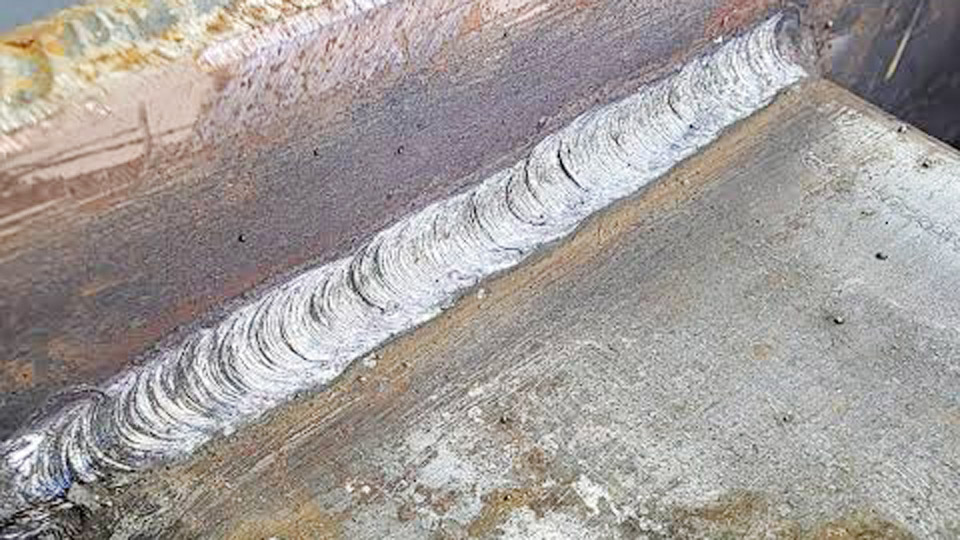
Image by r/Welding
Why 7018 Produces Hard Zones and Residual Stress on Cast Iron
Carbon Dilution and Martensite Formation
Gray cast iron contains graphite flakes that dissolve into the molten weld pool. When that high-carbon liquid mixes with the low-carbon 7018 deposit and then cools rapidly, the carbon-enriched region transforms into untempered martensite.
Hardness readings in the fusion line often exceed 50 HRC, far above the ductility of either base metal. This hard band becomes the preferred crack path under any tensile or bending stress.
Thermal Expansion Mismatch
Steel expands and contracts more freely than cast iron. As the joint cools from welding temperature, the steel side tries to shrink while the cast-iron side resists.
The resulting residual tensile stress concentrates at the toes of the weld and in the brittle heat-affected zone. Without controlled cooling or a more ductile filler, the stress exceeds the fracture toughness of the joint.
Dilution Limits of Low-Hydrogen Electrodes
7018 is formulated for low-hydrogen performance on clean carbon or low-alloy steel. Its iron-powder coating and medium penetration produce relatively high dilution when run on cast iron.
Higher dilution raises the carbon level in the weld metal itself, further reducing ductility. Lower amperage and short beads reduce dilution but cannot eliminate the metallurgical incompatibility.
When 7018 Remains a Practical Option Versus Nickel Electrodes
Non-Critical, Non-Machined Joints
7018 can be considered only when the joint will never be drilled, tapped, or subjected to high cyclic loads. Examples include attaching a mild-steel mounting bracket to a heavy gray-iron casting that experiences primarily compressive service, or temporary structural repairs where appearance and future machining are irrelevant.
In these cases the lower cost and ready availability of 7018 outweigh the elevated cracking risk, provided heat input is tightly controlled.
Critical or Machinable Service
Any joint that must be machined after welding, or that will see tension, bending, or thermal cycling, requires a nickel-based electrode. ENi-CI (approximately 99 % nickel) produces a soft, ductile deposit that can be drilled and tapped.
ENiFe-CI (55 % nickel) offers higher strength and lower cost while still remaining far more crack-resistant than 7018. Lincoln’s Tech-Rod 99 and Tech-Rod 55 are standard choices for these applications. Using 7018 in place of nickel on critical work simply transfers the failure risk to the field.
Hybrid Buttering Approach
A common professional compromise is to butter the cast-iron surface with a nickel electrode first, then complete the joint to the steel side with 7018.
The nickel layer acts as a ductile buffer that absorbs expansion differences and limits carbon migration into the final steel weld. This sequence reduces overall electrode cost while still protecting the cast-iron side.
Preheat, Interpass Temperature, and Cooling Strategy for Dissimilar Joints
Full Preheat Range for 7018 on Cast Iron
When 7018 is selected, preheat the entire casting—or as large a portion as practical—to 500–1200 °F. Never exceed approximately 1400 °F, the critical temperature range where additional metallurgical changes increase cracking tendency.
Uniform heating is essential; localized torch heating creates its own stress gradients. A temperature-indicating crayon or infrared thermometer confirms the target before the first arc is struck.
Keeping the Part Cool Instead of Hot
If the casting is too large or too constrained for full preheat, the opposite strategy is used: keep the part only warm enough that a bare hand can still rest on it (roughly 100–150 °F).
Deposit short ¾- to 1-inch beads, peen each bead immediately while it is still hot, then allow the area to cool below the hand-touch temperature before the next bead is placed.
This “cold” technique minimizes the time spent in the critical temperature range and reduces residual stress accumulation.
Controlled Cooling After Welding
Regardless of preheat level, the finished joint must cool slowly. Wrap the entire casting in dry sand, vermiculite, or insulating blankets. Rapid air or water cooling almost guarantees cracking.
On critical work, a post-weld stress-relief cycle at 1100–1200 °F followed by furnace cooling further lowers residual stress, although this step is rarely practical outside a shop environment.
Joint Preparation and Buttering Sequence When 7018 Is Used
Surface Cleaning and Crack Arrest
Grind or carbon-arc gouge all cracks back to sound metal. Drill stop holes at the ends of any remaining cracks. Remove oil, paint, and graphite residue with a solvent and a stainless-steel wire brush dedicated to cast iron; contamination produces porosity that acts as stress risers.
Bevel Geometry and Fit-Up
A 60–70° included-angle V-groove or U-groove provides adequate access while limiting the volume of weld metal. Leave a 1/16- to 1/8-inch root opening. Excessive root gap increases the amount of 7018 required and therefore the total heat input and residual stress.
Buttering the Cast-Iron Face
Deposit a thin layer of nickel electrode (or, if restricted to 7018, a series of short stringer beads) across the entire cast-iron bevel. Peen each pass. Allow the buttered surface to cool to interpass temperature before welding the steel side.
The butter layer reduces the carbon dilution that reaches the final weld metal and provides a more compatible interface for the subsequent 7018 passes.
Amperage and Technique Adjustments That Limit Heat Input
Current Selection for 1/8-Inch and 3/32-Inch 7018
Run 7018 at the low end of its normal range to minimize dilution and heat-affected-zone size. For 3/32-inch electrodes, 70–95 A is typical; for 1/8-inch electrodes, 90–125 A depending on position.
Higher currents increase admixture of cast-iron carbon and enlarge the hard zone. DC electrode positive remains the preferred polarity for arc stability and penetration control.
Short-Bead, Skip-Welding Sequence
Never deposit continuous beads longer than one inch. Skip to a distant location after each bead so the previous area can cool. Fill all craters completely; crater cracks are common initiation sites.
Maintain a short arc length (approximately equal to electrode diameter) to reduce atmospheric nitrogen pickup and further limit heat input.
Immediate Peening
While the bead is still cherry red, peen the surface with a blunt-nosed air hammer or ball-peen hammer. Peening stretches the weld metal, counteracting shrinkage stress. Stop peening once the metal cools below red heat to avoid work-hardening the surface.
Post-Weld Evaluation and Decision Criteria for Acceptability
Visual and Magnetic-Particle Inspection
After slow cooling, clean the weld and inspect under good light. Look for toe cracks, crater cracks, and incomplete fusion. Magnetic-particle testing reveals subsurface cracks that visual inspection misses.
Any crack that cannot be ground out and re-welded under the same controlled procedure indicates the joint is unsuitable for 7018 and must be redone with nickel electrode.
Hardness Mapping Across the Fusion Line
A simple file or portable hardness tester quickly identifies the hard martensitic band. Readings above approximately 40–45 HRC in the heat-affected zone confirm that the cooling rate or dilution was excessive. Such joints should be limited to non-critical compressive service or replaced.
Service Load Assessment
If the joint will experience tension, bending, impact, or repeated thermal cycles, the residual risk of delayed cracking remains high even after a visually acceptable 7018 weld.
In those cases the correct decision is to remove the 7018 deposit and re-weld with ENiFe-CI or ENi-CI, accepting the higher electrode cost in exchange for long-term reliability.
Wrapping Up
Selecting 7018 for cast-iron-to-steel joints is a calculated compromise that works only under narrow conditions: non-critical service, strict heat-input control, short beads, peening, and slow cooling.
When those conditions cannot be met, or when the joint must be machined or carry tensile loads, nickel electrodes remain the metallurgically correct choice.
Advanced practice often combines both: a nickel butter layer on the cast iron followed by 7018 fill on the steel side, delivering ductility where it is needed most while controlling cost on the remainder of the joint.
FAQs
Can you weld cast iron to mild steel with 7018?
Yes, but only for non-critical joints. Use heavy preheat or the short-bead “keep cool” method, peen every pass, and cool slowly. Nickel electrodes are preferred for any joint that will see tension or require machining.
What preheat temperature is needed for 7018 on cast iron?
500–1200 °F for the full-preheat method. Do not exceed about 1400 °F. If preheat is impossible, keep the casting only hand-warm and deposit short beads with peening.
Is nickel rod better than 7018 for cast iron to steel?
Yes. ENi-CI or ENiFe-CI electrodes produce far more ductile welds that resist cracking and can be machined. 7018 is a lower-cost alternative only when cracking risk is acceptable.
What amperage should I use for 1/8″ 7018 on cast iron?
Stay at the low end of the range—typically 90–125 A—depending on position. Lower current reduces carbon dilution and heat-affected-zone hardness.