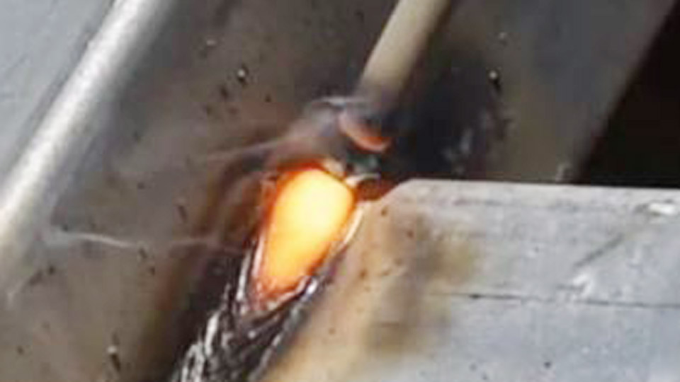
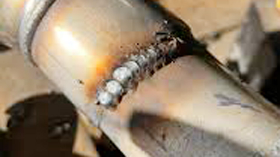
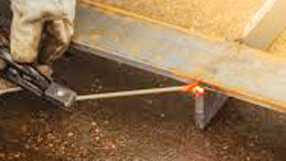
Burn-through happens in seconds when a stick arc sits too long on 16- or 18-gauge exhaust tubing. The wall melts, a hole opens, and the joint is ruined before a continuous bead can form.
Learning how to weld exhaust pipe with stick welder equipment requires accepting that SMAW is not the ideal process for thin-wall tubing, then applying the narrow set of parameters and techniques that keep heat input low enough to succeed.
Correct electrode diameter, amperage, polarity, fit-up, and intermittent welding determine whether the repair holds pressure or leaks under heat and vibration.
These decisions matter because most under-vehicle exhaust work occurs in awkward positions with limited access, where a portable stick machine is often the only tool available.
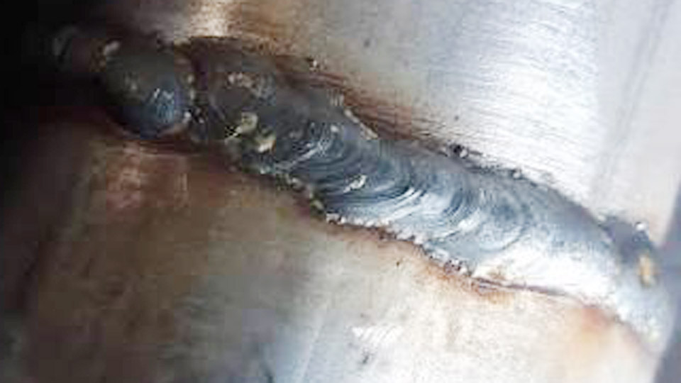
Image by fb/I See You Don’t Know Shit About Welding
Selecting the Right Electrode and Diameter for Thin Exhaust Tubing
Exhaust tubing typically measures 0.048–0.065 inch wall thickness. Any electrode larger than 3/32 inch deposits too much heat and metal for reliable control.
Why E6013 Is the Primary Choice
E6013 produces a soft, stable arc with shallow to medium penetration and low spatter. The rutile coating allows easy restriking and smooth slag removal—critical when working in short bursts under a vehicle.
On clean or lightly scaled mild-steel or aluminized exhaust, 1/16-inch or 3/32-inch E6013 keeps the puddle manageable at the lowest usable currents.
When E6011 Becomes Necessary
E6011 digs through heavier rust, scale, or residual coatings that E6013 struggles to penetrate. Its cellulosic coating creates a more forceful arc, so the risk of burn-through rises. Restrict E6011 to sections that cannot be cleaned thoroughly, and stay at the low end of its amperage range.
Avoid E7018 on thin exhaust; its higher deposition and low-hydrogen requirements demand currents that routinely open holes.
Diameter Limits That Matter
1/16-inch electrodes give the greatest margin against burn-through but are harder to find and more difficult to strike on some machines. 3/32-inch is the practical everyday size for most DIY and field repairs. Anything 1/8 inch or larger is unsuitable for standard exhaust tubing.
Correct Amperage and Polarity Settings That Prevent Blowouts
Amperage must stay at the absolute bottom of the electrode’s operating range. Excess current is the single most common cause of failure.
Practical Amperage Windows
For 1/16-inch E6013 start at 30–45 A. For 3/32-inch E6013 begin at 40–60 A and rarely exceed 70 A. E6011 of the same diameters runs 10–15 A higher. Test every combination on scrap of identical thickness and coating before touching the vehicle. The correct setting produces a quiet, controllable puddle that freezes quickly once the arc is broken.
Polarity Choice for Reduced Penetration
DC electrode negative (DCEN / straight polarity) concentrates more heat in the electrode and less in the base metal. When the machine allows it, DCEN is preferred for thin exhaust.
DCEP increases penetration and is useful only on slightly thicker flanges or when the joint needs extra fusion. AC machines require the higher end of the listed ranges and tighter technique to maintain arc stability.
Grounding and Circuit Considerations
Place the work clamp on clean metal as close to the joint as possible—preferably on a vice-grip or temporary clamp attached to the pipe itself. Long ground paths or painted surfaces cause arc instability at the low currents required, leading operators to raise amperage and create holes.
Joint Preparation and Fit-Up Decisions That Determine Success
Poor fit-up multiplies heat problems. Gaps force the operator to linger or weave, both of which overheat the thin wall.
Cleaning Requirements
Remove aluminized coating, rust, and scale to bright metal with a flap disc or wire wheel. Residual aluminum or heavy oxide produces porosity and erratic arc behavior. Clean at least ½ inch on each side of the joint line.
Butt Joint vs Sleeve Joint
A tight butt joint with near-zero gap works when both ends are square and solid. A short sleeve or slip-joint section provides internal backing, supports thin edges, and gives a larger heat sink. Sleeve joints are the more reliable choice on deteriorated tubing. Keep any gap under 1/16 inch; larger openings require excessive fill metal and heat.
Alignment and Tacking Sequence
Clamp or magnet the joint so the pipes remain concentric. Place four to six small tacks equally spaced around the circumference. Each tack should be only long enough to hold alignment. Allow the metal to lose its red color before the next tack.
Misalignment after tacking is corrected by breaking the offending tack and re-fitting rather than forcing the joint with additional heat.
Stitch Welding Technique for Controlling Heat Input
Continuous beads are almost never successful on standard exhaust wall thickness. Heat must be managed by deliberate interruption.
Short-Bead Length and Cooling Cycle
Deposit a bead ½ to 1 inch long, break the arc, and move to a cooler section of the joint—preferably 180 degrees opposite. Wait until the previous weld has lost its visible red heat before returning. This skip or stitch pattern prevents the cumulative temperature rise that melts the wall.
Arc Length, Angle, and Travel Speed
Maintain an arc length no longer than the electrode diameter. A longer arc spreads heat and increases the chance of burn-through.
Hold a shallow 10–15 degree drag or slight push angle so the arc energy travels along the joint rather than digging straight into the thin wall. Travel speed must be brisk; lingering to “fill” a gap is the fastest way to open a hole.
Overlap and Multi-Pass Strategy
Each new short bead should slightly overlap the previous solidified weld. The already-deposited metal acts as a heat sink and reduces the thermal load on the base tubing. On thicker flanges or after a sleeve is in place, a second light pass can be added once the joint has cooled, but the first pass must already be continuous and leak-free.
Handling Common Joint Types Under a Vehicle
Access and orientation change the practical sequence even when the fundamental parameters stay the same.
Horizontal and Vertical Pipe Sections
On horizontal runs, begin at the bottom and work upward in short segments so gravity assists slag control. Vertical sections favor downhill travel for thinner walls because the puddle freezes faster; uphill requires even lower amperage and stricter bead length limits.
Flange and Muffler Connections
Flanges are usually thicker than the tubing. Weld the tubing-to-flange joint first with the thin-wall technique, then address the flange face if needed. Muffler slip joints benefit from a short internal sleeve if the original wall has thinned.
Overhead or Restricted Positions
Overhead work on exhaust demands the lowest possible amperage and the shortest possible arc-on time. Position the body so the electrode can be held steady; fatigue leads to longer dwell times and holes. Chip slag thoroughly between every restart—trapped slag becomes a leak path under exhaust pressure and thermal cycling.
Diagnosing Weld Quality and Correcting Defects
Visual and functional checks reveal problems before the system is fully reassembled.
Signs of Excess Heat
A hole, a paper-thin section, or heavy undercut indicates amperage or dwell time was too high. Grind the damaged area back to solid metal, re-fit if necessary, and restart with shorter beads and lower current.
Incomplete Fusion and Porosity
Cold, ropey beads or visible porosity usually result from insufficient cleaning, long arc length, or amperage set below the stable range. Raise current slightly, shorten the arc, and ensure the joint is bright metal. Porosity on aluminized tubing often traces to incomplete removal of the coating.
Leak Testing
After the joint cools, apply soapy water while the system is under slight pressure or while the engine idles. Bubbles locate pinholes or incomplete fusion. Small defects can be closed with additional short stitches after thorough cleaning; large defects require cutting out and re-fitting.
When Stick Welding Exhaust Is Practical Versus Switching Processes
Stick welding remains useful for roadside or field repairs, heavily contaminated metal, or situations where shielding gas cannot be protected from wind. It is slower, produces more slag, and carries a higher risk of burn-through than MIG with 0.023-inch wire or TIG.
If the pipe wall is already paper-thin from corrosion, cutting back to solid metal and installing a proper sleeve or replacing the section is safer than forcing a stick weld. On stainless exhaust, specialized electrodes (E308L or E309L) are required; mild-steel rods will corrode rapidly.
Wrappin g Up
The decisive factors for a successful stick-welded exhaust joint are electrode diameter no larger than 3/32 inch, amperage held at the bottom of the usable range, DCEN polarity when available, near-zero joint gap, and strict adherence to short, interrupted beads with cooling time between them.
Operators who master heat management on scrap of identical thickness can produce serviceable, leak-free joints even with basic equipment.
Advanced practice consists of deliberately creating and then repairing small burn-through holes on scrap so the recovery sequence becomes automatic under a vehicle.